3-23
Current Leads Voltage
Phase = +90˚
PF = 0 Lead
Vars = -1.0 • VA
W=0
Voltage Leads Current
Phase = -90˚
PF = 0 Lag
Vars = +1.0 • VA
W=0
Phase = +135˚
PF = -.707 Lead
Vars = -.707 • VA
W = -.707 • VA
Phase = +45˚
PF = +.707 Lead
Vars = -.707 • VA
W = +.707 VA
Phase = 180˚
PF = -1.0
Vars = 0
W=-VA
Phase = 0˚
PF = 1.0
Vars = 0
W=VA
Phase = -135˚
PF = -.707 Lag
Vars = +.707 • VA
W = -.707 • VA
Phase = -45˚
PF = +.707 Lag
Vars = +.707 • VA
W = +.707 • VA
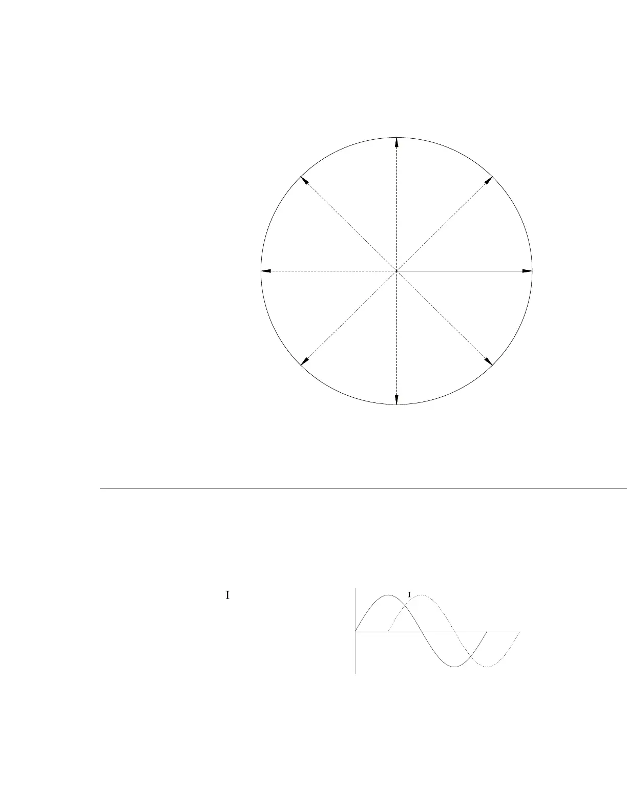
Conventions Used in the 1040C:
PowerFactor=Cosθ
Vars = Vrms • Irms • Sin (-θ)
Watts = Vrms • Irms • Cos θ
VA = Vrms •
rms
Where: θ (Theta) = Phase Angle between
voltage and current. A negat
number indicates that current
is lagging voltage.
Example:
Figure 12
Phase, Power Factor, and VAR Conventions
Employed by the 1040C Panel Meter Calibrator
Phase Angle = -90˚
V