2-37
2.8.3.3 FRONT PANEL KEY TEST
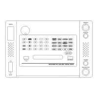
All of the front panel PMC keys and the knob are checked for correct operation in this test. The
knob check is performed first. The PMC will display the message KNOB = XXX. As the knob is
rotated the number represented by XXX will cycle from 0 to 255, increasing as the knob is rotated
clockwise and decreasing as the knob is rotated counter-clockwise. When the knob operation
check is completed press the ENTER key to continue. During the front panel key test the name of
a control key is displayed and the operator must respond by pressing the indicated key. If the
control key operates correctly, the next key name is displayed; otherwise no action occurs and the
test halts at this point. Corrective maintenance is required in the circuit area of the faulty key in
order for the test to proceed. The key test can be terminated any time after the RESET key is
tested by pressing RESET (assuming the RESET key is operable).
2.8.3.4 RAM/ROM & PHASE TEST
Key elements of the control section are tested including: (1) read only memory (ROM), which
holds the PMC control program; (2) random access memory (RAM), which stores measurement
and operational data; (3) electrically erasable ROM (EEROM) which stores calibration and user
data; and (4) frequency generation and phase control. The EEROM is not directly tested in this
test routine but is tested for loss or alteration of data during power on and is tested each time the
RESET function and calibration operations are performed. As mentioned above, it is assumed that
a catastrophic fault is not present in the Z80 control processor so that it is able to function, at least
in a limited way, to perform the control tests.
2.8.3.4.1 ROM Test
A check sum test is performed on the control ROM to verify that the control program is intact. All
of the bytes for the control program, present in the ROM are added to form a sum, which is
compared with a stored value in the ROM. A FAIL message is displayed if a difference is
detected.
2.8.3.4.2 RAM Test
All bytes in the RAM are exercised to verify correct operation. A FAIL message is displayed if a
fault is detected.
2.8.3.4.3 Phase Test
The frequency generation and phase control counter circuitry are checked in this diagnostic test.
The test is restricted to the signal generation circuits and does not include operation of the PMC
voltage and alternating current output amplifiers. A FAIL message at the end of this test would
indicate a fault in the processor counter or frequency generation circuitry.
2.8.3.5 REFERENCE & ADC TEST
The analog to digital converter (ADC) test measures the internal precision 100 mV reference and
verifies the operation of the sample and hold and analog to digital conversion circuitry.

 Loading...