2-9
2.5.1 Power Factor/Phase Operating Procedure
CAUTION - Power Factor/Phase Meter Calibrations - The following procedure employs initial
output values of 120 volts and 5 amperes, at 60 Hz and 0°, 30° and 60° phase values. A full meter
calibration would include other values.
The phase convention in the PMC is set by the following equations:
Voltage: V(t) = Vo sin wt
Current: I(t) = Io sin (wt + Θ)
Power: Vrms Irms cos Θ
VARS Vrms Irms sin (-Θ)
Power Factor: Cos Θ
Where Θ = phase angle in degrees between voltage and current
Phase Angle Sign of Power Sign of VARS Power Factor
0<Θ <90
+ - Lead +
90 < Θ <180
- - Lead -
-180 < Θ <-90
- + Lag -
-90 < Θ <0
+ - Lag +
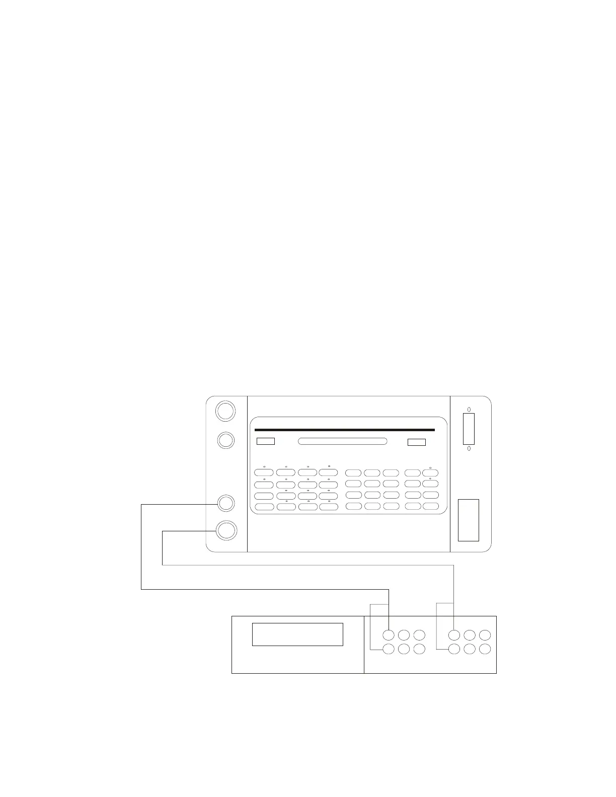
Turn the PMC off, connect the PMC to a power factor or phase meter (See Fig. 2.2 below) and
proceed with the steps in Table 2.2.
AUX. V.
VOLTAGE
CURRENT
1040C PANEL METER CALIBRATOR
REMOTE
DRANETZ 305C
VI
I
V
Figure 2.2 – PMC CONNECTIONS FOR TESTING POWER FACTOR/PHASE
OPERATION