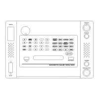
1-1
Model 1040C
Panel Meter Calibrator
1.0 General Information
This manual provides specifications and operating instructions for the Model 1040C Panel Meter
Calibrator (hereinafter referred to as the PMC) manufactured by Arbiter Systems.
1.1 Introduction
This section contains general information regarding the application, technical characteristics and
specifications of the PMC.
1.2 Application
The Model 1040C PMC is a “ruggedized,” portable instrument that contains precision AC/DC
voltage and current sources which are suitable for in-place calibration of a wide variety of panel
meters. The voltage and current sources may be operated singly for calibration of voltmeters,
ammeters, and frequency meters, or simultaneously for calibration of wattmeters and power factor
or phase meters. Also, two voltage outputs are provided that produce AC voltage with either 0ø or
180ø phase relationships for calibration of synchroscopes. Keypad controls with LED indicators,
a 20-character alphanumeric display, and internal memory permit easy setup or recall of voltage,
current, power, frequency and phase values. The 10 digit keypad and units keys allow entry of the
exact output value desired. A rotary knob and modify keys are provided for fine adjustments.
1.3 Technical Characteristics
The PMC consists of a stand alone card cage assembly that is shock mounted in a rugged,
watertight aluminum case. In the center of the card cage assembly is a passive motherboard that
provides the necessary daughter board and I/O interconnections. Ten plug-in daughter boards
each connect to the motherboard with two, 40-pin, pin and socket connectors. The daughter
boards contain all of the circuitry required to output the calibrated voltages and currents.
An extender card is available for use with any of the daughter boards to facilitate trouble-shooting.
The display module has two printed circuit cards that provide the user interface through a set of
function and numeric keys, indicator LED's, a rotary knob and a twenty character alphanumeric
vacuum fluorescent display.
The display module is connected to the motherboard with a 34-conductor ribbon cable. A fan,
high-voltage toroidal transformer and switching power supply are hard-mounted to the card cage
and connected to the motherboard with pin and socket connectors. Two cables each, three meters
long, are provided to facilitate connection to remotely mounted panel meters. A Hand Held Unit
is included that permits remote operation of the PMC when calibrating panel meters mounted in
confined locations. All functions of the 1040C including internal alignment are controllable over
the General Purpose Interface Bus (GPIB) IEEE-488-1978 and IEEE-488.1.

 Loading...