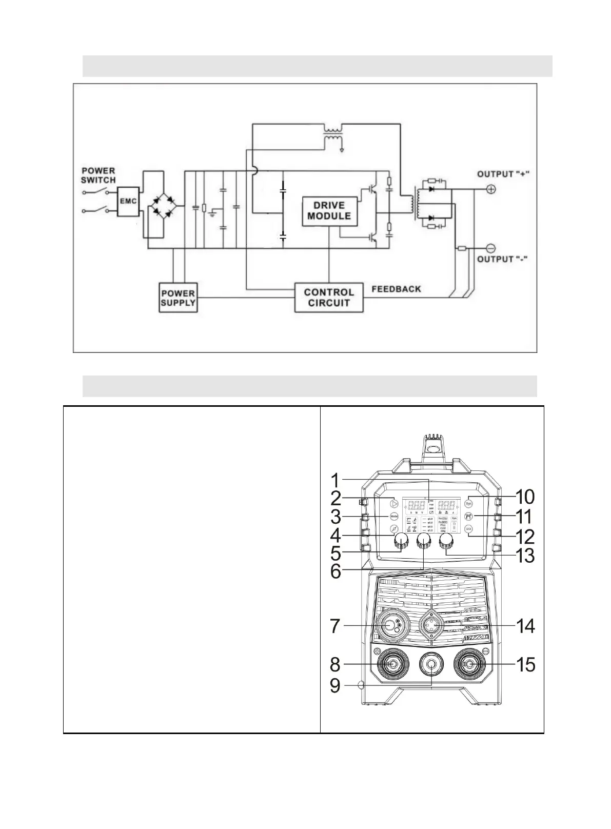
8. ELECTRICAL SCHEMATIC DIAGRAM
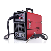
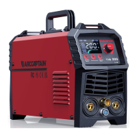
9. OPERATION CONTROL AND DESCRIPTION
1. Digital screen display area
2. Parameter setting and display area for spot
welding time, parameter group storage,
voltage and so on
3. Welding process selection area
4. MIG diameter selection area
5. Voltage and spot welding time adjustment
knob
6. Current and wire feed speed adjustment
knob
7. Euro connector for torch
8. "+" output terminal
9. Polarity changeover plug
10. Synergic selection button
11. MIG operation mode selection area
12. MIG material selection area
13. Inductance adjustment knob
14. Socket for Spool gun
15. "-" output terminal