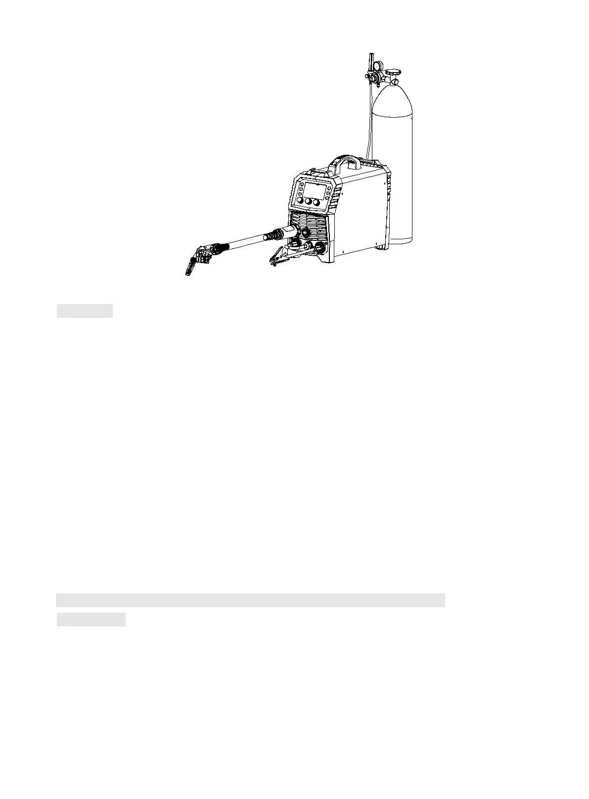
Sketch map of MIG Welding
Operation
1) After being installed according to the above method, and the power switch being switched on, the
machine is started with digital display on and the fan working. Open the cylinder valve, and adjust the
flow regulator to get the proper gas flow.
2) Press 2T/4T button to select desired mode.
2T: Press torch trigger to activate wire feeding. After arc ignition, start welding based on set
wire feed speed and voltage. Release torch trigger to stop wire feeding and welding. Gas is
turned off after 0.5S.
4T: Press torch trigger to activate wire feeding. After arc ignition, start welding based on set
wire feed speed. When releasing torch trigger, welding continues. Press torch trigger again,
welding still continues. After releasing torch trigger, wire feeding and welding stops. Gas is
turned off after 0.5S.
3) Operators can adjust burn-back time and post-flow time based on actual demands, see 9.3 for
specific setting.
10.5 Installation and operation for Gasless self-shielded arc welding
Installation
1) Insert the welding torch into the Euro connector for torch in MIG on the front panel of the machine,
and tighten it.
2) Insert the cable plug with work clamp into the “+” output terminal on the front panel of the welding
machine, and tighten it clockwise.
3) Insert the quick plug on the front panel into the “-” output terminal, and tighten it clockwise.
4) Install the wire spool on the spindle adapter and tighten the cover of spindle. Make sure that the