groove size of wire feed roll matches the contact tip size of the welding torch and the wire diameter
being used. Release the pressure arm of the wire feeder to thread the wire through the liner, into the roll
groove and then into the liner of central connector. Adjust the pressure arm to ensure no sliding of the
wire. Too high pressure will lead to wire distortion, which will affect wire feeding. Press the Inching
button to thread the wire out of the contact tip on the torch. (Gasless self-shielded arc welding
applies flux-cored self-shielded welding wire, which requires knurling rolls)
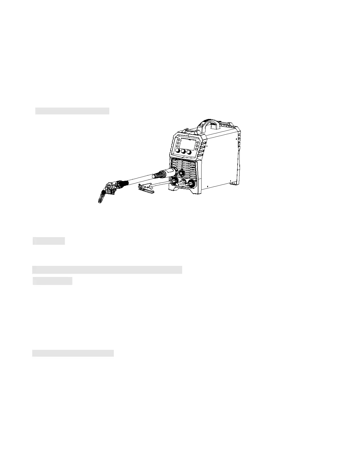
Sketch map of installation
Sketch map of Gasless Self-shielded Arc Welding
Operation
The operation is the same as MIG operation except that there is no gas option.
10.6 Installation and operation for TIG welding
Installation
1) As it is shown in the figure, TIG torch is connected to negative pole on the front panel, while
workpiece is connected to positive pole. Please note that quick connector should be tightened.
2) Connect Argon cylinder and gas inlet hose of TIG torch. Open the gas valve after achieving suitable
gas flow. Attention: Make sure connection is well to prevent gas leakage.
(Note: At TIG, gas is not controlled by built-in gas valve; therefore, gas should be connected to gas inlet
hose of TIG torch outside the machine)
Sketch map of installation