Avon Protection 8 DAS775571AA Version 9, December 2015
GR 13313 CR121804
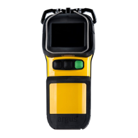
3.3 System Configuration (Charger Front)
1. Docking bay 2 (spare battery) 5. Camera latching mechanism
2. Docking bay 1 (camera with battery) 6. USB port (front)
3. Camera eject mechanism 7. Charging status LEDs
4. Camera release button 8. Front cover (removable)
Up to six chargers can be powered in a “daisy chain” configuration. Connections should
be made via the green power connectors located underneath the removable front cover.
The “daisy chain” power circuit contains a replaceable 10 A fuse. This is also located
underneath the removable front cover. See section 4.3 for installation details.
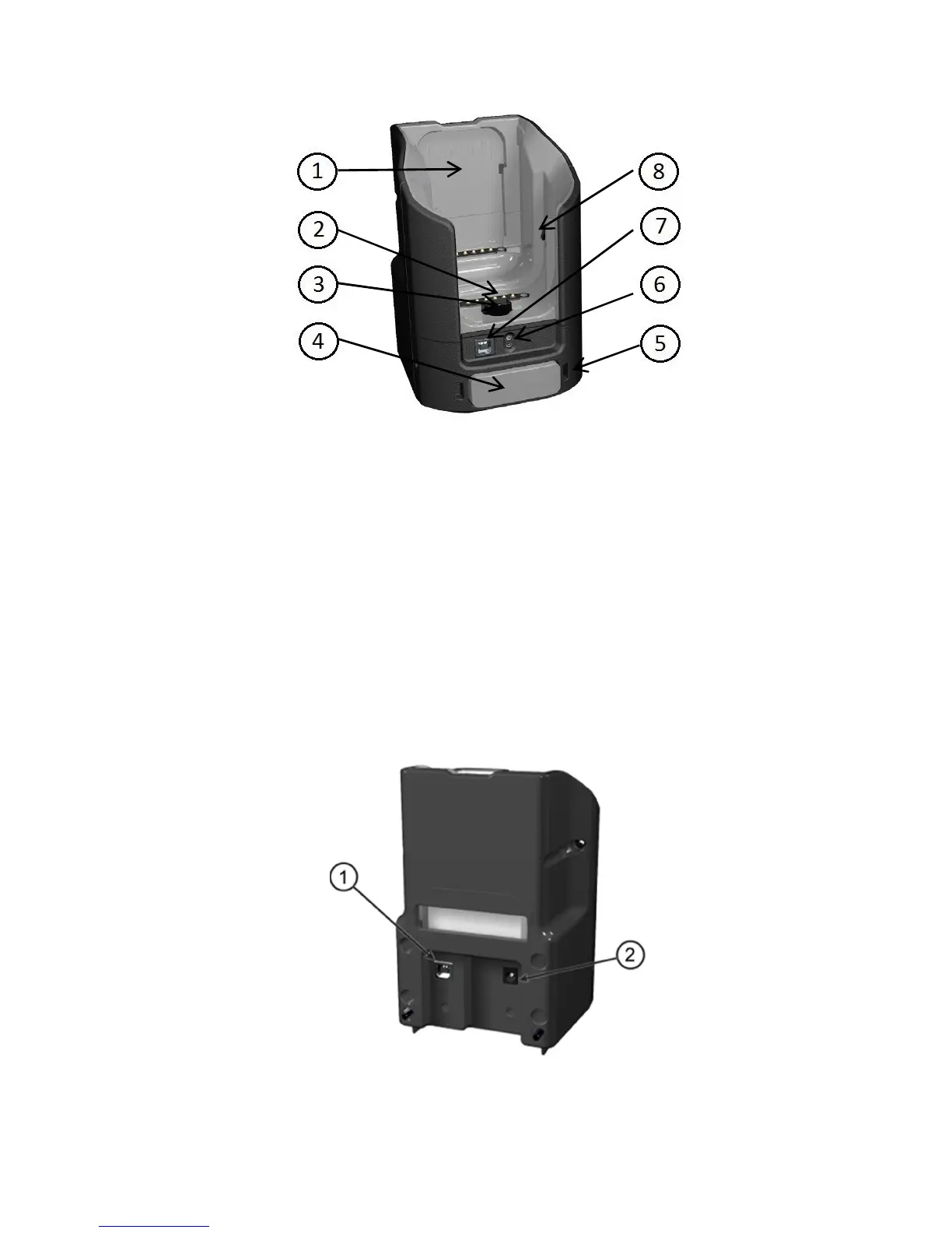
3.4 System Configuration (Charger Rear)
1. USB port (rear)
2. Power connector (single charger only)