INSTALLATION
/ 14
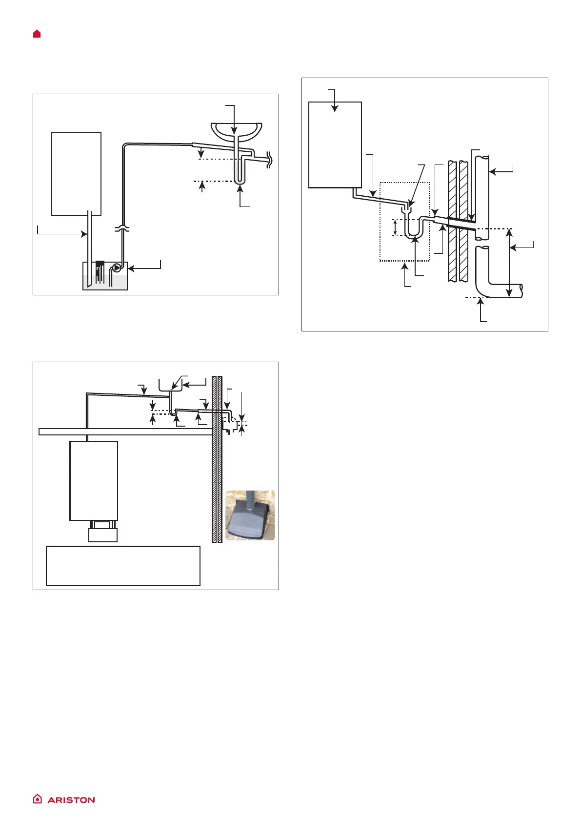
4. Connection of condensate discharge pipe to external soil
and vent stack.
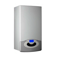
3. Connection of condensate pump - typical method (NB
manufaturer’s detail instructions shoud be followed.
Note: Requirements for any external pipe work shall be
followed.
75
450
1
8
9
5
11
7
6
4
3
10
2
75mm
min
22mm Ø
3
4
5
1
2
KITCHEN UNITS
1
4
6
8
9
3
7
5
10
2
75
≥25
1. Boiler
2. Visible air break
3. 75 mm trap
4. Visible air break and trap
not required if there is
a trap with a minimum
condensate seal of 75
mm incorporated into the
boiler.
5. Soil and vent stack.
6. Inverter.
7. 450 mm minimum up to
three storeys
8. Minimum internal diameter
19 mm.
9. Pipe size transition point
10. Minimum internal diameter
30 mm
11. UV resistan, Water/
weather proof insulation.
1. Boiler
2. Visible air break at plug
hole
3. 75 mm sink, basin, bath or
shower waste trap.
4. Sink, basin, bath or
shower with integral
overow.
5. Open end of condensate
discharge pipe direct into
gully 25 mm min below
grating but above water
level; end cut at 45°. Note:
the maximum external
condensate discharge
lengh is 3 metres.
6. Minimum internal diameter
19 mm.
7. Pipe size transition
8. Minimum internal diameter
30 mm
9. Water/weather proof
insulation.
10. Fit drain cover/leaf guard
1. Condensate discharge from boiler
2. Condensate pump
3. Visible air break at plug hole.
4. Sink or basin with integrated overow.
5. 75 mm sink waste trap.

 Loading...