13
Warning
The exhaust gas ducts must not be in contact with or close to
inflammable material and must not pass through building
structures or walls made of inflammable material.
When replacing an old appliance, the flue system must be
changed.
Important
Ensure that the flue is not blocked.
Ensure that the flue is supported and
assembled in accordance with these
instructions.
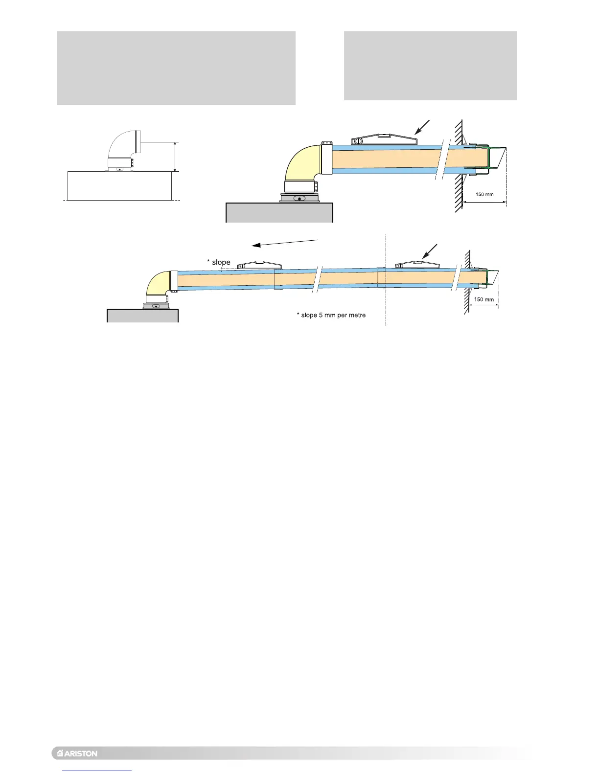
2.9.1 FITTING THE COAXIAL FLUE
(Ø 60 / 100 HORIZONTAL)
SEE PAGE 19 FOR MAX AND MIN FLUE RUNS
Installation without extension
Installation with extension
Fig. 2.11
Fig. 2.12
Level
Level
PART NO: 3318073
CONTENTS:
1
X SILICONE O-RING (60mm)
1
X ELBOW (90
O
)
2X WALL SEALS (INTERNAL & EXTERNAL)
1X FLUE PIPE INCLUDING TERMINAL (1 METRE - 60/100)
2
X FLUE CLAMPS
4X SCREWS
2x Seals
Once the boiler has been positioned on the wall, insert
the elbo
w into the sock
et and rotate to the required
position. NO
TE
:
It is possible to rotate the elbow 360
o
on
its vertical axis.
Using the flue clamps, seals and screws supplied (
Fig
2.13) secure the elbow to the boiler.
The 1 metre horizontal flue kit (3318073) supplied is
suitable for an exact X dimension of 823mm.
Measure the distance from the face of the external wall
to the face of the flue elbow (X - Fig 2.10), this figure
must now be subtracted from 815mm, you now have
the total amount to be cut from the plain end of the flue.
Draw a circle around the outer flue and cut the flue to
the required length taking care not to cut the inner flue,
next cut the inner flue ensuring that the length between
the inner and outer flue is maintained. (Fig 2.13).
e
.g.
X = 555mm
823-555 = 268mm (Length to be cut from the plain
end of the flue).
 Loading...