32
In the boiler, it is possible to monitor the correct operation
of the flue exhaust/air intake, checking for a loss of
general pressure in the system. Through the use of a
differential manometer connected to the test points of the
comb
ustion chamber, it is possible to detect the DP of
operation of the air pressure switch.
The v
alue detected should not be less than 0.55 mbar
under conditions of maximum thermal power (see Section
3.4), in order for the boiler to function proper
ly and
without interr
uption.
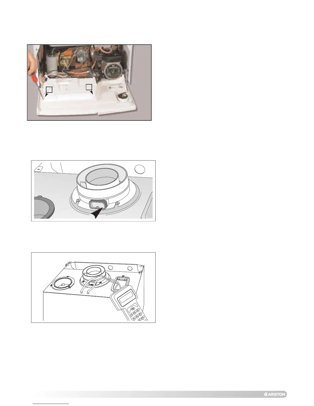
The flue connector has two apertures, readings can be
taken for the temperature of the combustion products and
of the combustion air, as well as of the concentrations of
O2 and CO
2, etc.
To access these intakes it is necessary to unscrew the
front screw and remove the metal plate with sealing
gasket.
It is possible to activate the flue test mode (maximum
output) by pressing and holding the RESET button “D” for
10 seconds,
“
s
s
c
c
” will be shown on the display. The boiler
will return to normal operation after 5 minutes. The boiler
can be returned to normal operation sooner by switching
the boiler off and on again.
3.4 COMBUSTION ANALYSIS
3.5 PR
ODUCT
OF
COMB
USTION
DISCHARGE MONITORING
FU008A
FU009A
To access the areas in which adjustments are made, it is
n
ecessary to open the control panel, as indicated in
SECTION 2.12, then remove the rear inspection cover by
u
nscrewing the two screws
“
A”
.
Access is thereby
provided to the P.C.B. and to the following components:
1. The power supply cable connector;
2. The fuses;
3
. The soft-light potentiometer must be set to ensure
c
orrect ignition;
4. The maximum thermal heating power potentiometer
adjustable by the minimum to maximum power
(already calibrated in the factory to 70% of the
maximum thermal power in Central Heating mode);
5. The dip switch for adjusting the ignition delay (anti-
cycling) feature, which can be set from off to 2
minutes (set in the factory to off);
6.
Fan/Pump Over-run (Electrical Diagram). When the
jumper is set to position A the Fan and Pump over-run is
activated. (The jumper is factory set in position B)
7. The time clock connector.
NOTE:SEE PAGE 27 FOR DIP SWITCH LOCATION.
3.3 OPERATIONAL
ADJUSTMENTS
A
A
The boiler allows the convenience level to be increased in
the output of domestic hot w
ater by means of the
“COMFOR
T”
function.
This function keeps the secondary
exchanger warm during the periods in which the boiler is
inactive, thereby allowing the initial water drawn to be at a
higher temper
ature
.
The function ma
y be activ
ated b
y pressing tur
ning the
COMFORT switch ‘E’ on the control panel from E to C
(see section 2.10).
3.6 COMFOR
T
MODE
 Loading...