47
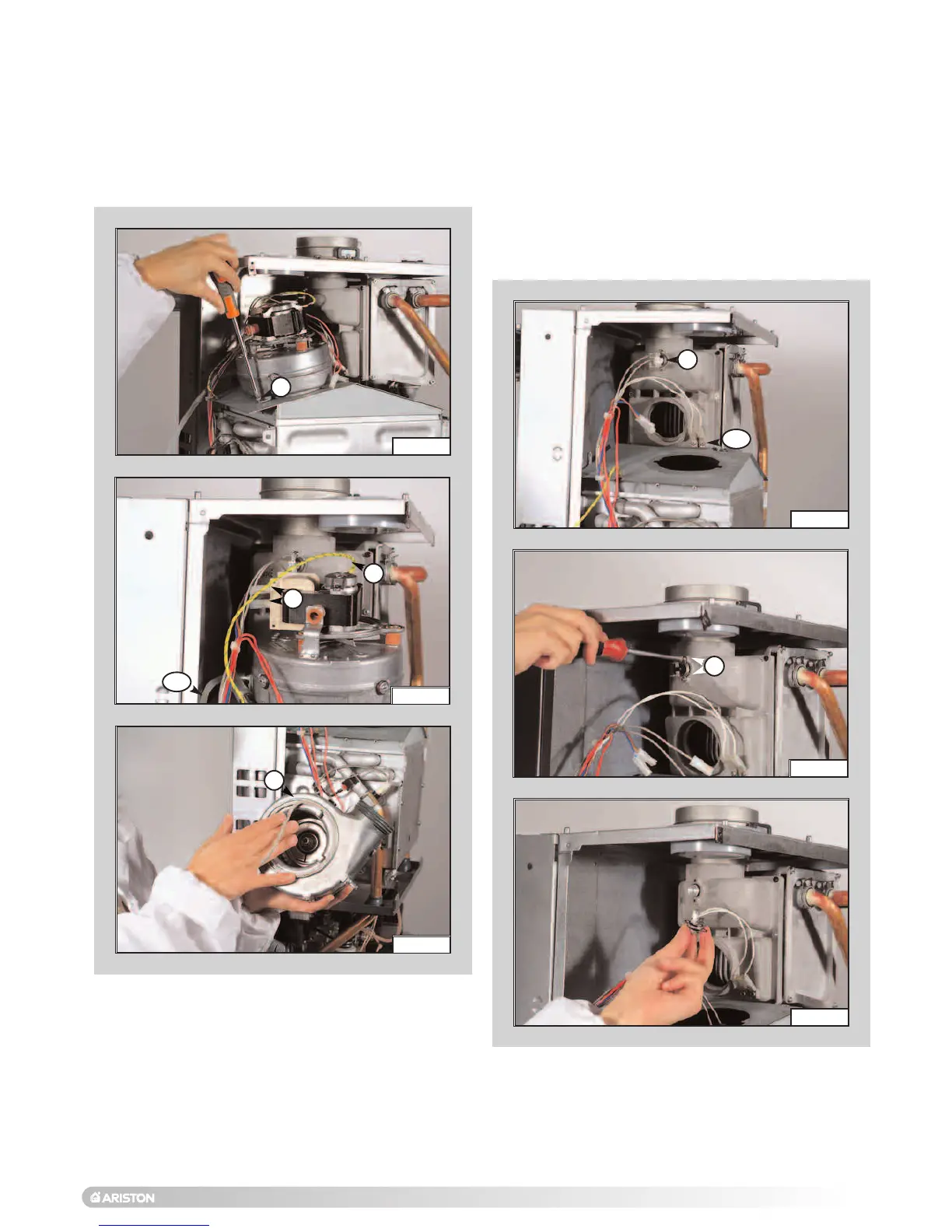
1. Remove screw “P” (FIG.6.24);
2. Disconnect electrical connections “Q” and silicone pipe
“Q1” (FIG.6.25);
3
.
R
emove fan and gasket “R” (F
I
G
.
6.26).
4. Reassemble in reverse order, ensuring the gasket “R”
is seated correctly.
6.3.6 Removing the fan
1. To remove the flue sensor, disconnect electrical
connections “S” (FIG.6.27);
2
.
R
emove screws “T” and remove the flue sensor
(
F
IG.
6.28 - 6.29).
3. To remove the condensate sensor, remove screws “T1”
and remove the condensate sensor (resistor wire)
(F
IG.6.27);
6.3.7 Removing the flue sensor and
condensate sensor
FI
G
. 6.24
FIG. 6.25
FIG.
6.26
R
Q
Q
P
FIG. 6.27
FIG.
6.28
FIG.
6.29
S
T
S1
Q1
 Loading...