ARKEL Elektrik Elektronik Ltd. Şti. www.arkel.com.tr
08.2012
ADrive
33
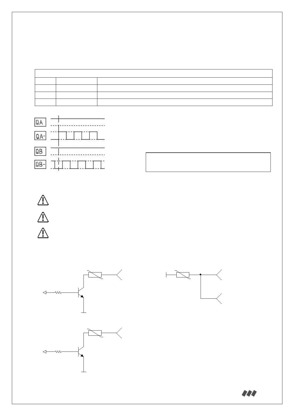
13.2.4.4. Absolute encoder simulation outputs:
If the lift controller needs the absolute encoder for shaft copying then use the absolute encoder
simulation outputs on ENCABIT-Plus module.
Absolute encoder simulation outputs:
QA- Encoder –A Encoder phase A inverse
QA Encoder A Encoder phase A (+24V)
QB- Encoder -B Encoder phase B inverse
QB Encoder B Encoder phase B (+24V)
The resolution of the encoder simulation outputs is identical with the encoder resolution.
Use a shielded twisted pair cable for connection. Connect the cable shield to the inverter
housing.
To minimize the distortion, cable lengths should be as short as possible.
Encoder simulation cable channel should be separated from motor and other power cables.
Minimum distance between cables should be at least 10cm.
ENCABIT-Plus absolute encoder simulation output circuit:
R101
PPTC0.1A
QA-
...
...
Q3
Q4
R102
10K
R103
10K
GND
GND
R104
PPTC0.1A
R105
PPTC0.1A
24V
QB-
QA
QB
Output signal high: Max. 24V (max. 100mA)
Output signal low: Min. 0.6V
 Loading...