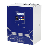
13.2.2.2. Additional transistor outputs:
Additional transistor output terminals:
Additional transistor
output 1
Lower load direction (with lowest power consumption). This
output is renewed during each brake releasing.
TO1 = 24V: Direction UP (Car is lighter than counterweight)
TO1 = Open: Direction DOWN (Car is heavier than counterweight)
Additional transistor
output 2
V < 0,3 m/s. This output can be used for interlocking during run-
in with open doors.
TO2 = 24V: V < 0,3 m/s
TO2 = Open: V >= 0,3 m/s
Note: 0 or -24V terminals on ADrive processor board may be used as common (GND) of
additional transistor outputs.
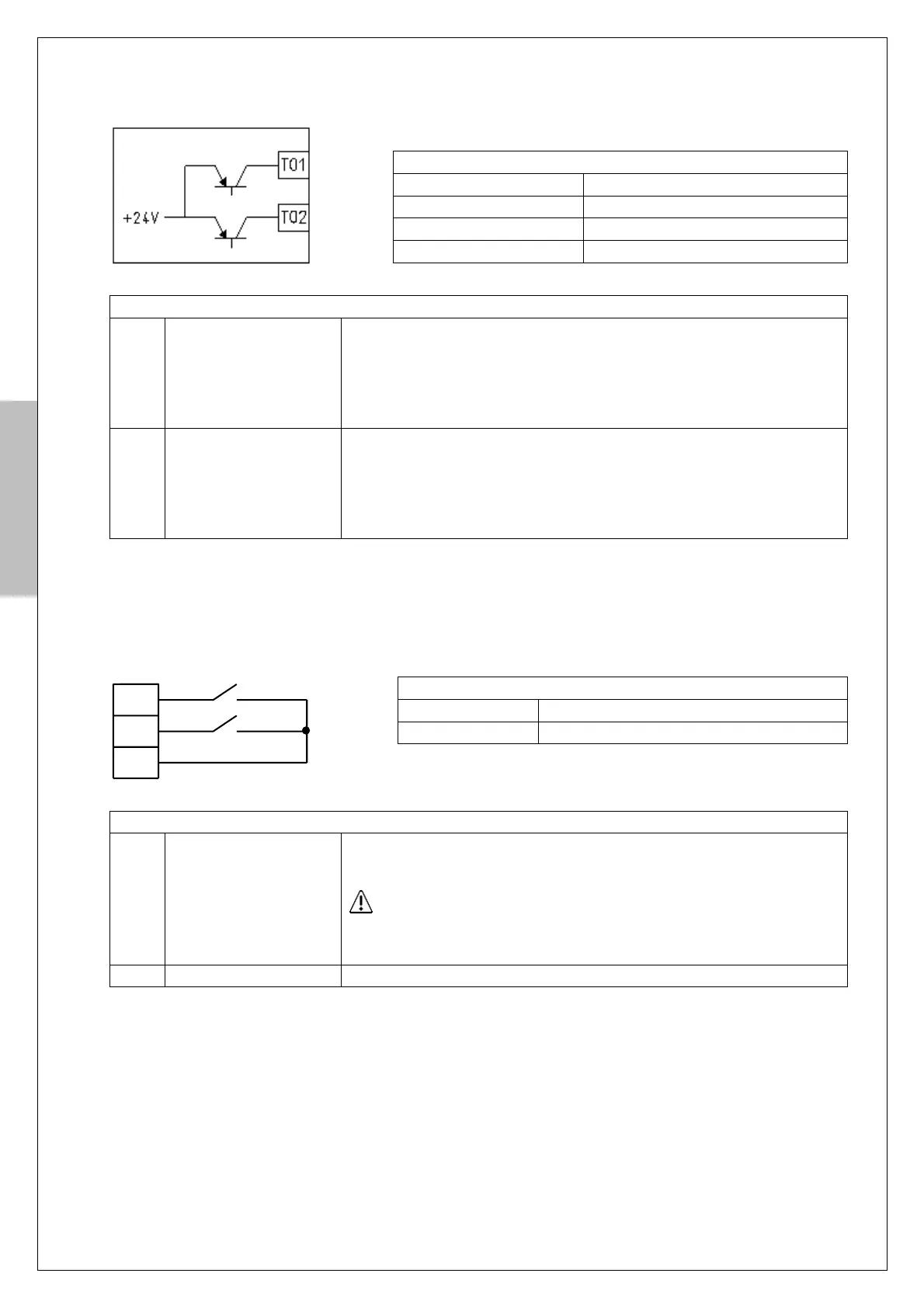
13.2.2.3. Additional digital inputs:
Additional input terminals:
Activation input for battery operation. When 24Vdc is applied to
this input, inverter goes into battery operation mode.
This input must not be activated when the 3-phase AC supply
is connected to inverter. For more information about battery-
operated evacuation see Chapter 13.3.
This input is reserved for future use.
Note: Additional inputs (CI1, CI2) and outputs (TO1, TO2) are available in version V2.5 and
higher of processor board.
Transistor output specifications:
Digital input specifications: