5-12 CHP Max™ Headend Optics Platform Chassis, Controllers and Power Supplies Rev D
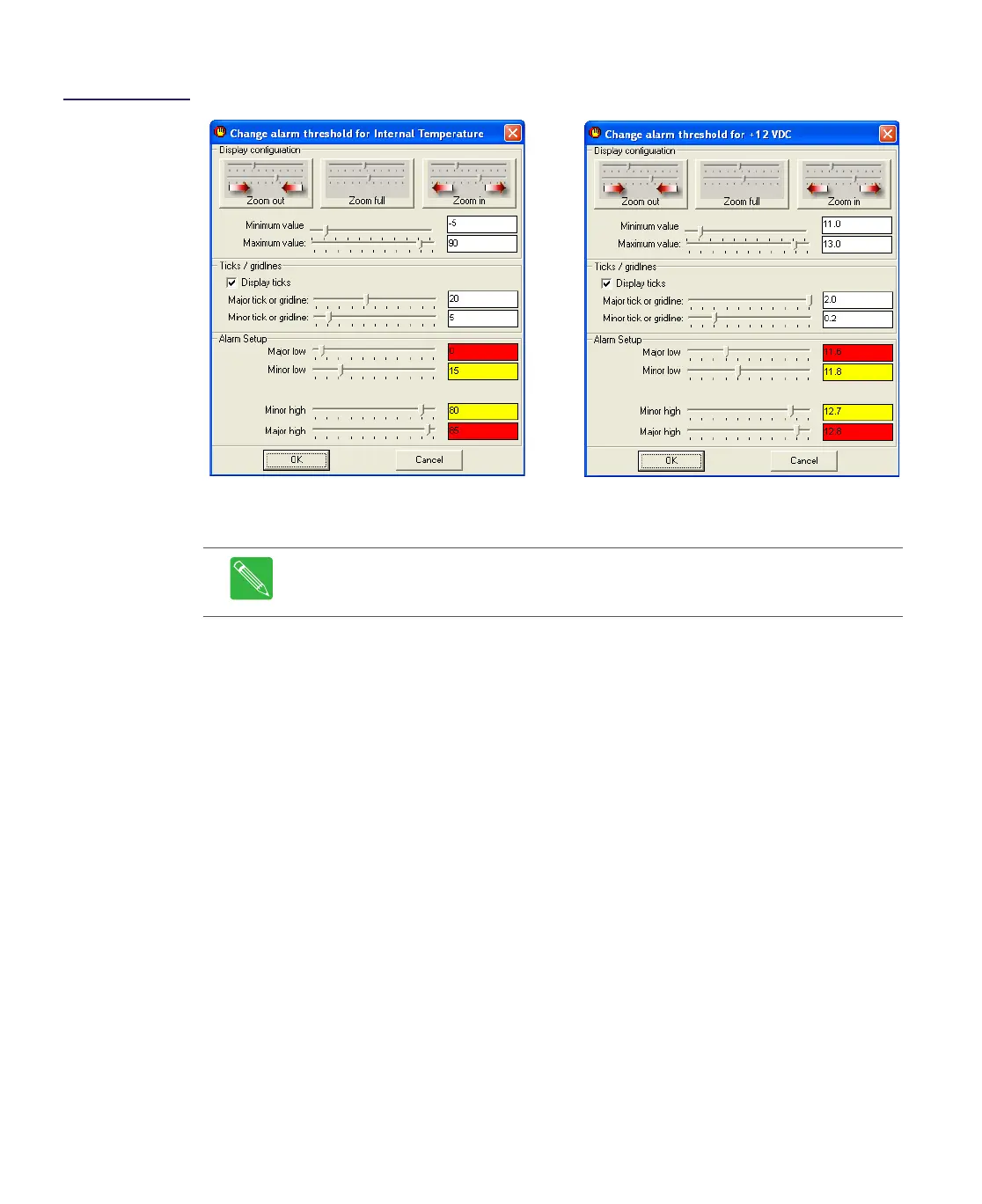
Figure 5.9
Internal
Temperature and
+12V
DC Threshold
Limits
8. Right click on either the Fan 1 current or Fan 2 current meter and select Configure
from the shortcut menu. Refer to Figure 5.10.
9. In the Alarm Setup area, drag the slider or enter the desired alarm limit value for the
Major low, Minor low, Minor high, and Major high. Click OK to save these alarm limit
values.
Note The alarm thresholds for Fan 1 current and Fan 2 current are not
independent. Changing the alarm threshold value on either of the fan meters will
automatically update the alarm threshold on the other fan meter.
+12VDC Alarm Threshold Settings
Internal Temperature Alarm Threshold Settings