2-8 CHP Max™ Headend Optics Platform Chassis, Controllers and Power Supplies Rev D
Functional Description
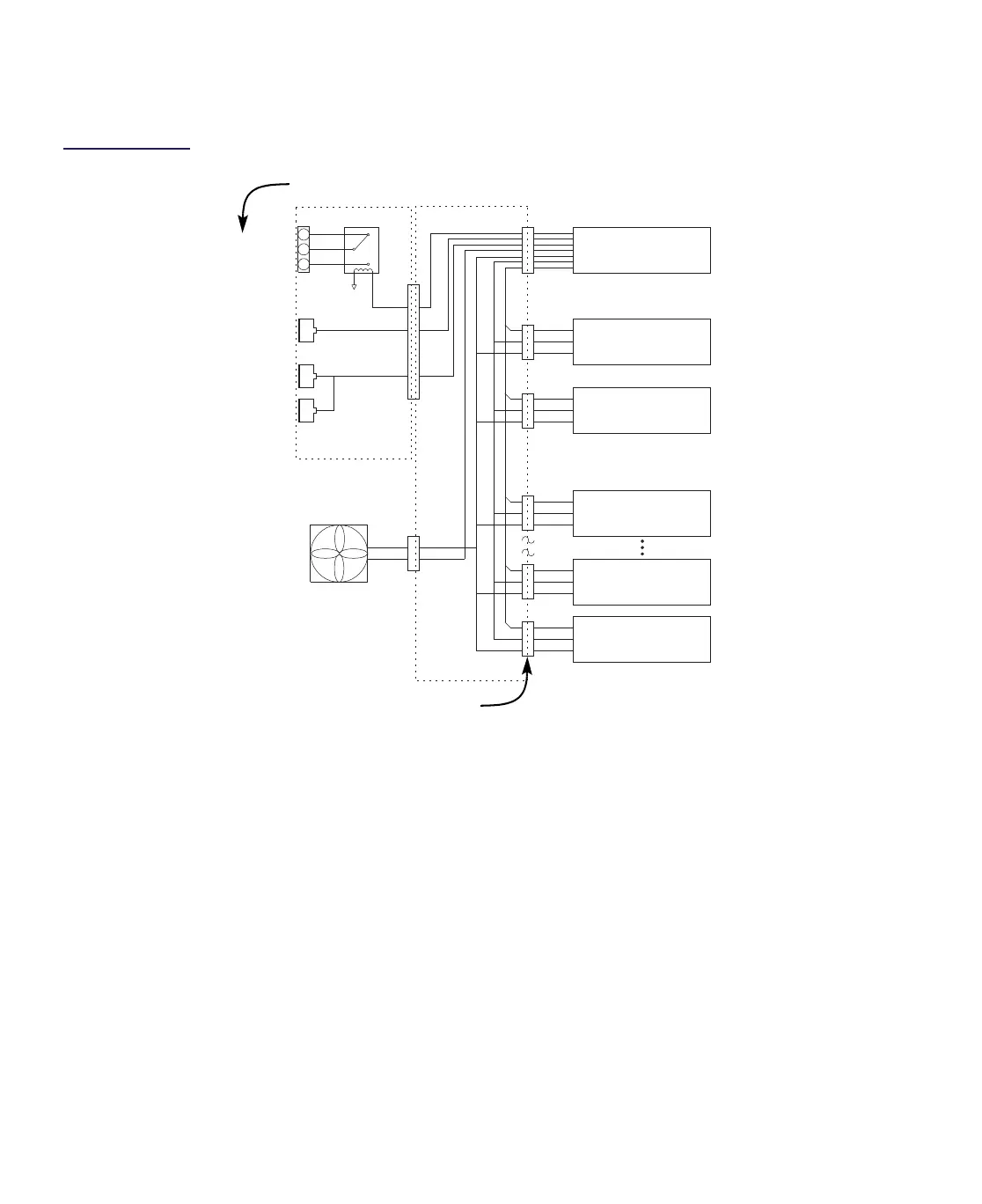
Figure 2.4
CHP Max System
Block Diagram
DC Voltages
The CHP Max power supply feeds DC voltages into the backplane through a multi-pin
DC/Communications connector. These voltages travel along the DC power bus, entering each
application module through multi-pin DC/Communications Interfaces.
Chassis Fans
Eight single speed chassis fans (P/N 0625734-1) are provided with chassis (P/N
CHP-CHASSIS-19) and always operate at full speed. The eight dual-speed chassis fans (P/N
CHP-QFANKIT) provided with chassis (P/N CHP-CHASSIS-19Q, CHP-CHASSIS-19Q-B,
CHP-CHASSIS-19S-B, CHP-CHASSIS-19S, or CHP-CHASSIS-19U) operate in the low-speed
mode when the fan’s sensed exhaust temperature of the chassis is less than 30° C and
operates in the high-speed mode when the exhaust temperature is above 30°C.
Shelf
Interconnect
SNMP
Ethernet
Local
Alarm
Com
N. O.
N. C.
Chassis Fan
(1 of 8
shown)
Aux Backplane
Main Backplane
Application Module 1
Application Module 2
Application Module
10
Power Supply 1
Power Supply 2
Management Module
(CMM or SMM)
Power Bus
Fan Current sense
SPI Bus
RS-485
Module Select Lines (12)
DC/Communications Interfaces
Please note that the contacts on the Local Alarm terminal block are reversed.