2-12 CHP Max™ Headend Optics Platform Chassis, Controllers and Power Supplies Rev D
3. If desired, position the optional tablet PC bracket assembly (P/N 1500376-001) over
the CHP chassis and align the mounting holes of the bracket with the mounting holes
of the CHP chassis. Install and tighten all four mounting flange screws securely.
Refer to the rack manufacturer’s recommended torque specifications.
4. Connect an appropriate ground wire from the common rack ground to one of the
ground studs on the left of the rear of the chassis (see Figure 2.2 on page 2-5). A
10-32 UNF nut is required (not supplied) to secure the wire’s ground lug to the
ground stud.
5. Repeats Steps 1 through 4 to install each of the remaining chassis in the CHP system.
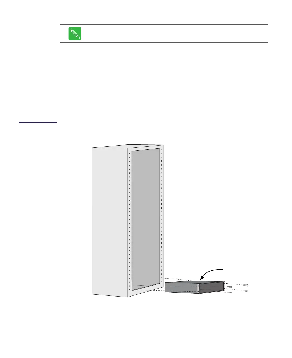
Figure 2.6
Installing a Chassis
in a Standard 19
Inch Rack
Note The tablet PC bracket assembly (P/N 1500376-001) can NOT be installed in
front of a CHP chassis with the optional handle kit (P/N CHP-HANDLE-KIT) installed.
CHP Chassis
Standard EIA 19 inch Rack
Install chassis from the bottom of
the rack toward the top of the
rack to prevent the rack from
toppling.