3-20 CHP Max™ Headend Optics Platform Chassis, Controllers and Power Supplies Rev D
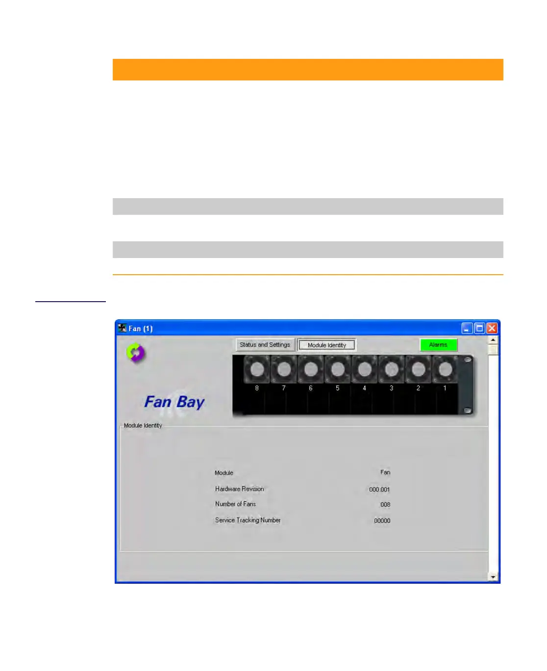
Figure 3.11
Chassis Fan Bay
Module Identity Tab
Display
Fan 1-8 Current Displays the 12V
DC current of each of the eight chassis fans in mA.
Configure Sets major low, minor low, minor high, and major high alarm limits of all
eight fan currents. Changing the alarm limit of one fan will change the
alarm limits of the other seven fans to the same alarm limit.
Show info Lists the four alarm thresholds and graphical display configuration
information.
Show history Displays a graph of the output current vs. time.
Save history Saves output current data points vs. time to an Excel file format.
Module Identity tab
This tab only provides status. Refer to Figure 3.11 on page 3-20 to see the various module
parameters.
Alarms tab
This tab lists all major and minor alarms as shown in Figure 3.12 on page 3-21.
Table 3.6 Controls and Functions of the Craft Management Software (cont’d)
Control Function