EasyManua.ls Logo

ASCOM NIRC4-xMN - User Manual

ASCOM NIRC4-xMN
30 pages
Print Icon
To Next Page IconTo Next Page
Loading...
INSTALLATION GUIDE
Room Controller 4 (NIRC4-xMN)
Question and Answer IconNeed help?

Do you have a question about the ASCOM NIRC4-xMN and is the answer not in the manual?

Summary

Safety Symbols and Information

Important Safety Instructions

Provides critical safety instructions and symbols for installation and operation.

Product Description and Capabilities

General Installation Requirements

Mounting the NIRC4-xMN Unit

Mounting Base to Backbox

Step-by-step guide for attaching the NIRC4-xMN base to EU and North American style backboxes.

Mounting Base Directly to Wall

Instructions for mounting the NIRC4-xMN base directly onto a flat wall surface without using a backbox.

Connections and DIP Switch Configuration

Room Bus Type Selection

Auxiliary Power Supply Options

Room Bus Cable Preparation

NU-series Room Bus Connector Termination

Mounting NU-series Connectors

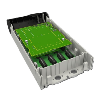
Step-by-step guide to seating 8-pin block connectors onto the active room bus terminals.

NI-series Room Bus Connector Termination

Mounting NI-series Connectors

Step-by-step guide to seating 8-pin block connectors onto the active room bus terminals for NI-series.

LAN Network Connection (T-568 B)

LAN Cable Ferrite Clamp Installation

Explains how to place the ferrite cable clamp around the LAN cable near the RJ45 connector.

Optional Connections and Expansions

Optional Power Supply via PoE Midspan

Details powering the NIRC4-xMN using an auxiliary 24VDC power supply via a power injector.

NILDx LED Lamp Installation

Instructions for placing NILD2 or NILD4-RGB LED boards to function as a corridor lamp.

NIRX Receiver Board Installation

Details installing the NIRX wireless transceiver module for wireless nurse call functionality.

NIVP Voice Module Installation

Instructions for installing the NIVP4 voice module for speech functionality.

Wireless Gateway Configuration

Explains how to create a Wireless Gateway by connecting a NUREP to the NIRC4-xMN USB port.

Document Revision History

Overview

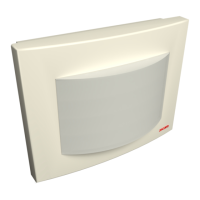
The Ascom Room Controller 4 (NIRC4-xMN) is a teleCARE IP controller designed to establish a decentralized node within an IP network, acting as a gateway between four digital room buses and the IP network. This device is compatible with NU-series modules, supporting up to 12 such modules per room bus.

Function Description:

The NIRC4-xMN serves as a central control unit in a teleCARE IP system, facilitating communication and functionality for various connected modules. It integrates with the IP network via a 100Mb Ethernet connection, supporting Power over Ethernet (PoE) for power input, or an auxiliary power supply through a PoE Midspan. The controller also provides firmware upgrade support for connected NU-series modules, ensuring system maintainability and future compatibility.

Beyond its core control functions, the NIRC4-xMN offers several optional expansion capabilities. It includes a connection for an optional wireless transceiver (NIRX), enabling wireless nurse call functionality. An optional voice module (NIVP4) can be integrated to support speech communication for NU-series modules. The device can also function as a corridor lamp, accommodating up to four LED boards (NILD2 and NILD4-RGB) behind a translucent dome cover, allowing for visual signaling and workflow indications. An integrated USB 2.0HS Host Port and Device Port provide connectivity for a Wireless Gateway, which, when combined with a NUREP, can establish a full wireless infrastructure supporting up to 12 Wireless Repeaters per gateway.

Important Technical Specifications:

  • Connectivity: 100Mb Ethernet connection, supporting PoE (IEEE 802.3af standard, up to 15.4W per port).
  • Module Compatibility: Compatible with NU-series modules (up to 12 per room bus) and NI-series modules.
  • Expansion Ports:
    • NIRX expansion connectors for wireless transceiver.
    • NIVP4 expansion connectors for voice module.
    • USB 2.0HS Host Port and Device Port for Wireless Gateway connection.
    • Four active room bus connectors (0-3) for NU-series or NI-series modules.
    • LED lamp connections (LEDO, LED1, LED2, LED3) for NILD2 and NILD4-RGB boards.
  • Power Input: PoE or auxiliary 24VDC power supply via a PoE Midspan.
  • Ingress Protection: IP40.
  • Fuse (for auxiliary power): 315mA slow-blow fuse (5x15mm or 5x20mm).
  • Cable Length (auxiliary power): Total cable length between power supply and NIRC4-xMN not to exceed 2.5 meters (8.2 feet).
  • DIP Switches: For bus type selection (NI or NU-series modules).
  • Buttons: Mode button, Reset button.
  • Indicators: Status LED.

Usage Features:

  • Flexible Mounting: The NIRC4-xMN base can be mounted onto various EU and North American-style backboxes, or directly onto flat wall surfaces where backboxes are unavailable. The mounting process involves placing the base, aligning it, and securing it with screws.
  • Cable Management: Cables can be routed through a central hole or knockouts at the bottom or right side of the base. Proper stripping of cable jackets (150mm or 6 inches) is required for optimal fit. Wire holding clips within the housing help secure the room bus wires.
  • Bus Type Selection: A DIP switch on the circuit board allows users to select the appropriate bus type (NU-series or NI-series) for connected modules. This setting takes effect after a power cycle.
  • Auxiliary Power Option: For non-PoE LAN switch ports, an auxiliary 24VDC power supply can be used via a PoE Midspan. A jumper on the circuit board enables this functionality.
  • LED Corridor Lamp: The device supports up to four NILDx LED boards, which can be easily inserted into designated connection points. The position of the LED color is configured during system setup.
  • Wireless Gateway Integration: A Wireless Gateway can be created by connecting a NUREP to the NIRC4-xMN's internal USB 2.0HS Host Port using a Micro USB to Micro USB (OTG) cable. The OTG cable comes with a movable ferrite core for practical mounting.

Maintenance Features:

  • Firmware Upgrades: The NIRC4-xMN supports firmware upgrades for connected NU-series modules.
  • Regular Inspection and Cleaning: Due to the risk of dust buildup, regular inspection and cleaning of the NIRC4-xMN are required to prevent fire hazards. When performing maintenance in clinical areas, proper measures should be taken to avoid spreading dust or other particles.
  • Circuit Board Cooling: The NIRC4 circuit board can become hot during operation. It is important to switch off the device and allow the circuit board to cool down before servicing.
  • Fuse Replacement: For auxiliary power setups, an inline fuseholder with a 315mA slow-blow fuse is used. This fuse can be unscrewed and replaced if necessary.
  • Connector Compatibility: The manual provides pinout diagrams for 8-pin block connectors (NICT-8AA and NICT-8CA) for both NU-series and NI-series modules, aiding in correct cable termination and connection. It also highlights potential collision issues with NICT-8CA connectors and wire holding clips, suggesting the removal of the clip if needed.
  • Cable Management for NI-series: For NI-series modules, which require fewer wires, excess wires should be carefully stowed in the backbox to prevent short-circuits.

ASCOM NIRC4-xMN Specifications

General IconGeneral
BrandASCOM
ModelNIRC4-xMN
CategoryController
LanguageEnglish

Related product manuals