INSTALLATION GUIDE
Room Controller 4 (NIRC4-xMN) Optional Connections and Expansions
12.2 NILDx LED Lamp Placement
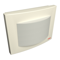
The NIRC4-xMN can also function as a corridor lamp supporting up to four NILD2 or NILD4-RGB LED boards.
Caution: Bright LEDs behind translucent dome cover. High brightness light is produced by
the LED boards that are placed onto the NIRC4-xMN circuit board. Do not stare into the light
when the translucent dome cover is removed.
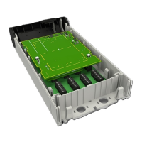
To place the NILDx LED board(s):
1. Remove the release liner from the two pieces of double sided tape at the back of the LED board.
2. Insert the LED board into the NIRC4-xMN. The pins on the LED lamp board are not in the center of the
board; therefore, it is important to make sure that the LED lamp board lines up with the guide marks on
the room controller PCB when the pins are inserted.
The LED lamp connection points are labelled LED0, LED1, LED2 and LED3. Any color LED
board (NILD2) or multi color workflow LED board (NILD4-RGB) can be plugged into any of the
connection points in the room controller. The appropriate position of the LED color is
determined during the system setup.
3. With the three pins inserted and the LED lamp board lined up with the guide marks, press the LED lamp
board flat onto the room controller PCB. Repeat the procedure on the other required LED lamp boards.
Figure 23. Insert LED boards
TD 93351EN / 21 March 2022 / Ver. B 23