INSTALLATION GUIDE
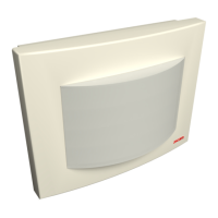
Room Controller 4 (NIRC4-xMN)
Contents
1 Symbols ......................................................................................................................................... 1
2 Description....................................................................................................................................2
3 Installation.....................................................................................................................................3
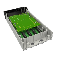
4 Mounting.......................................................................................................................................4
4.1 Mount the NIRC4-xMN base onto a backbox..........................................................................4
4.2 Mount the Base without a Backbox .......................................................................................5
5 Connections and DIP Switch Settings ..............................................................................................7
6 Setting the Room Bus Type Selection............................................................................................. 9
7 Enabling Auxiliary Power Supply ................................................................................................... 10
8 Preparing the Room Bus Cables..................................................................................................... 11
9 Terminating and Mounting Room Bus Connectors for NU-series Modules........................................ 12
9.1 To mount the active room bus connectors: ...........................................................................13
10 Terminating and Mounting Room Bus Connectors for NI-series Modules........................................ 15
10.1 To mount the active room bus connectors: .......................................................................... 16
11 LAN Connection (T-568B) ............................................................................................................ 18
11.1 Ferrite Clamp .................................................................................................................... 18
12 Optional Connections and Expansions ........................................................................................ 20
12.1 Auxiliary Power Supply via PoE Midspan .............................................................................20
12.2 NILDx LED Lamp Placement ...............................................................................................23
12.3 NIRX Receiver Board Placement.........................................................................................24
12.4 NIVP Voice Module Board Placement .................................................................................25
12.5 Wireless Gateway Configuration .........................................................................................26
13 Document History.......................................................................................................................27
TD 93351EN / 21 March 2022 / Ver. B