LAN Connection (T-568B)
INSTALLATION GUIDE
Room Controller 4 (NIRC4-xMN)
11 LAN Connection (T-568B)
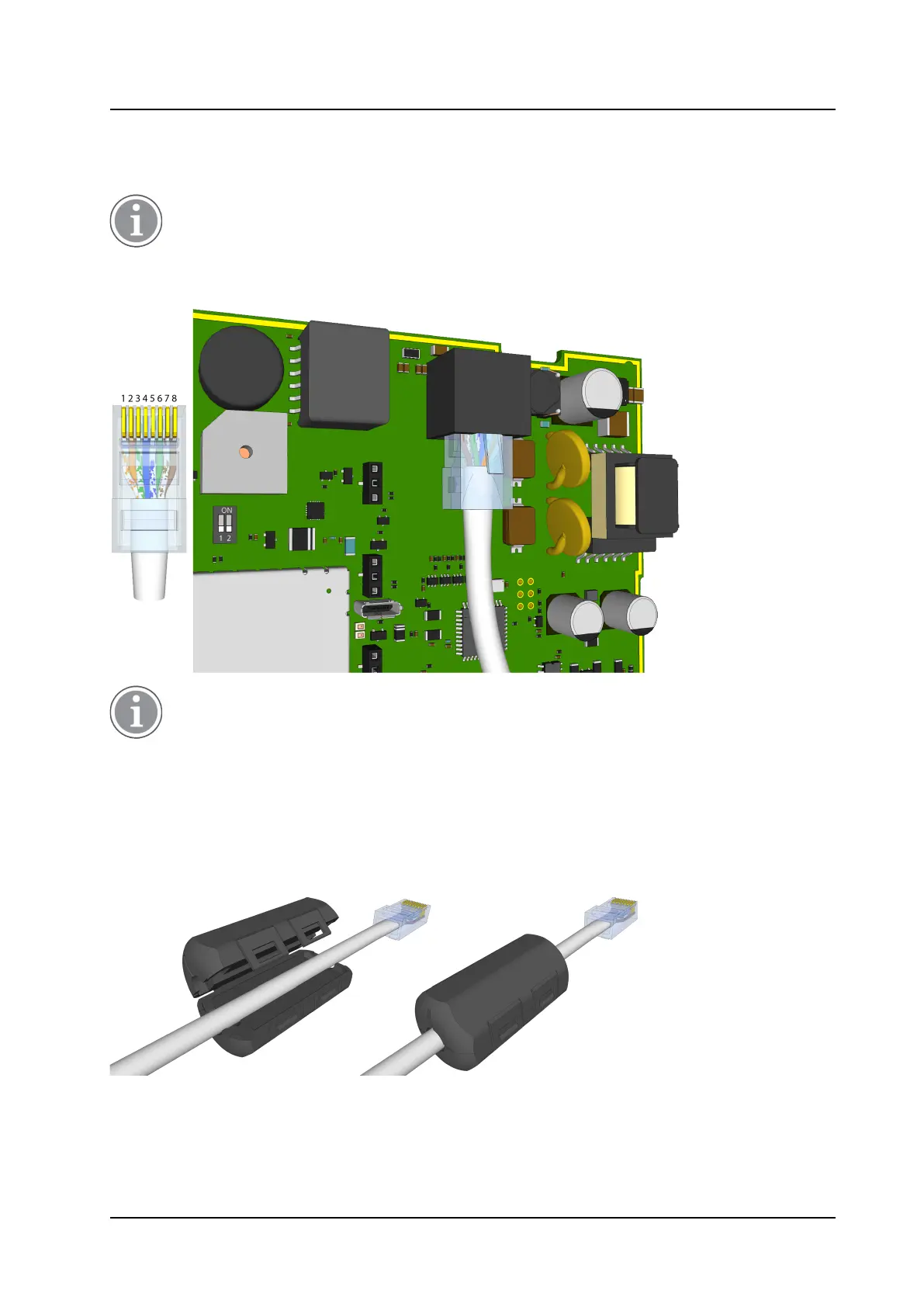
Connect a LAN cable using T-568B termination to the RJ45 Ethernet connector on the NIRC4 circuit board.
Power to the NIRC4-xMN is supplied using power over ethernet (PoE), plugging in the network
cable will automatically power on the NIRC4-xMN. Make sure all wire connections are made and all
optional expansion board(s) are placed before connecting the NIRC4-xMN to the LAN.
Figure 18. LAN connection
Make sure to connect the NIRC4-xMN to a quality PoE switch that complies with the EN 62368-1
product safety standard. In accordance to the IEEE 802.3af (PoE) standard, the PoE switch must be
able to support the delivery of power up to, but not exceeding a maximum of 15.4W per port
(NIRC4-xMN).
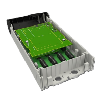
11.1 Ferrite Clamp
The NIRC4 comes with a ferrite cable clamp.
Figure 19. Ferrite cable clamp on the NIRC4 LAN cable
Place the ferrite cable clamp around the LAN cable close to the RJ45 connector entering the NIRC4.
18 TD 93351EN / 21 March 2022 / Ver. B