INSTALLATION GUIDE
Room Controller 4 (NIRC4-xMN) Connections and DIP Switch Settings
5 Connections and DIP Switch Settings
Before attaching the PCB to its base, make all wire connections and DIP switch settings. Be sure that
required cables are properly connected. The following figures show the locations for each cable.
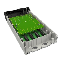
Figure 2. NIRC4-xMN circuit board - front
Legend
1. LED lamp (NILD2, NILD4–RGB) connections
2. Mode button
3. USB 2.0HS Device service port
4. Reset button
TD 93351EN / 21 March 2022 / Ver. B
7