Connections and DIP Switch Settings
INSTALLATION GUIDE
Room Controller 4 (NIRC4-xMN)
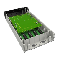
Figure 3. NIRC4-xMN circuit board - back
Legend
1. Wireless transceiver (NIRX) expansion connectors
2. DIP switches for bus type selection (NI or NU-series modules)
3. Buzzer
4. RJ45 Ethernet connector with PoE support and LEDs
5. Jumper for enabling auxiliary power supply
The jumper is only available on the NIRC4 with circuit board revision D or later.
6. Active room bus connectors (0-3) for connecting NU-series or NI-series modules
7. USB 2.0HS Host port for Wireless Gateway
8. Voice piggy back module (NIVP4) expansion connectors
9. Status LED
Caution: Hot surface. When operational, various surfaces on the NIRC4 circuit board can
become too hot to touch.
Switch off and let the circuit board cool down before servicing.
8 TD 93351EN / 21 March 2022 / Ver. B