37
4 - Operation
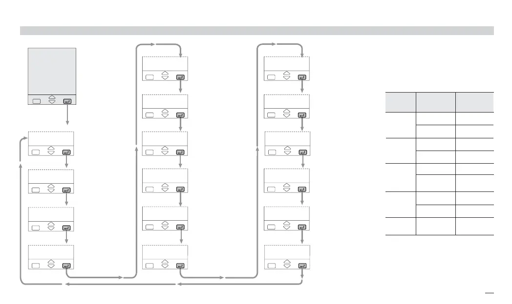
4.4.2 PARAMETERISATION - ALARMS MENU
Menu
AL
hy.3u
é 1
hy.3d
é 1
hy.4u
é 1
hy.4d
é 1
hy.2d
é 1
hy.2u
é 1
hy.Iu
é 1
4---
é 0
3---
é 0
2---
é 0
1---
é 0
tf1-
é 1
hy.Id
é 1
tf3-
é 1
tf2-
é 1
tf4-
é 1
Alarm threshold 1
[1] see table
Alarm threshold 2
[1] see table
Alarm threshold 3
[1] see table
Alarm threshold 4
[1] see table
Alarm 1 hysteresis
asymmetric upper
0…5% Span
in engineering units
Alarm 1 hysteresis
asymmetric lower
0…5% Span
in engineering units
Alarm 1 delay
OFF/1...9999
Alarm 2 hysteresis
asymmetric upper
0…5% Span
in engineering units
Alarm 2 hysteresis
asymmetric lower
0…5% Span
in engineering units
Alarm 2 delay
OFF/1...9999
Alarm 3 hysteresis
asymmetric upper
0…5% Span
in engineering units
Alarm 3 hysteresis
asymmetric lower
0…5% Span
in engineering units
Alarm 3 delay
OFF/1...9999
Alarm 4 hysteresis
asymmetric upper
0…5% Span
in engineering units
Alarm 4 hysteresis
asymmetric lower
0…5% Span
in engineering units
Alarm 4 delay
OFF/1...9999
Alarms
menu
Type and
adj. value
Mode
Number and
Parameter
Absolute
full scale
on input
Active high
-fs.H
Active low
-fs.l
Deviation
full scale
on input
Active high
-de.H
Active low
-de.l
Band
full scale
on input
Active in band
-bni
Active out
of band
-bno
L.B.A.
1…9999s
Active high
-lba
[1] A code, specifying the number
and the alarm type that has been
configured (see page 31), is
displayed. At this point, the user
must enter the threshold value,
according to the following table.
Absolute
full scale
on output
Active high
-OP.H
Active low
-OP.L
Note:
OP.H, OP.L absolute alarm
on output value (full scale)
can be associated only to
AL2, AL3 and AL4
x5-uk-ed5 17-09-2009 14:53 Pagina 37
 Loading...


