NETWORK-SWITCH-LP01 – Configuration Guide
U-0641-3675.docx – Issue: 01 complete, approved
Page 5 of 28
2.2 Hardware Settings
2.2.1 Fault Reporting
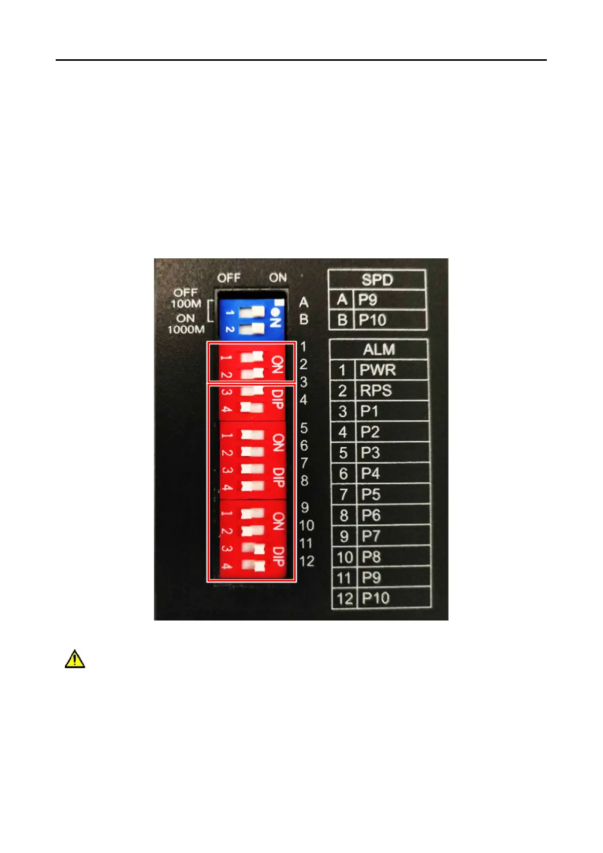
The network switch should be configured to monitor the Ethernet connections and power supply. This is
configured using DIP switches on the top of the unit.
1. Ensure switch 1 (PWR) and switch 2 (RPS) are ON.
2. Set switches 3 (P1) to 12 (P10) ON for each port that has a connection to the ASL Secure Loop, or
to a device that is part of the PAVA system.
The example below is configured for ASL Secure Loop connected to ports 9 and 10 (the SFP ports) and
VIPEDIA-12 connected to port 1.
For EN 54-16 compliance, the network switch must be configured to report faults as described
above and connected to an onboard or BMB01 fault contact input in the voice alarm system.
The PAVA system fault contact must be configured to active low.