Astraada DRV-24 frequency inverters Function Parameters
74
Detailed instruction of parameters
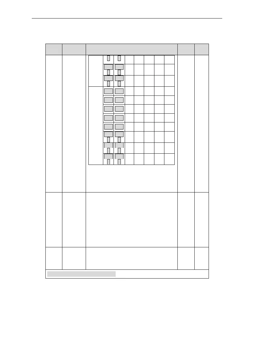
After the users select the corresponding
ACC/DEC time, the combining 16 binary bit will
change into decimal bit, and then set the
corresponding function codes.
Setting range: -0x0000~0xFFFF
0: Restart from the first stage; stop during
running (cause by the stop command, fault or
power loss), run from the first stage after
restart.
1: Continue to run from the stop frequency;
stop during running(cause by stop command
and fault), the inverter will record the running
time automatically, enter into the stage after
restart and keep the remaining running at the
setting frequency.
Multi-step
time unit
selection
0: Seconds; the running time of all stages is
counted by second
1: Minutes; the running time of all stages is
counted by minute
P11 Group Protective parameters
 Loading...