Astraada DRV-24 frequency inverters Function Parameters
81
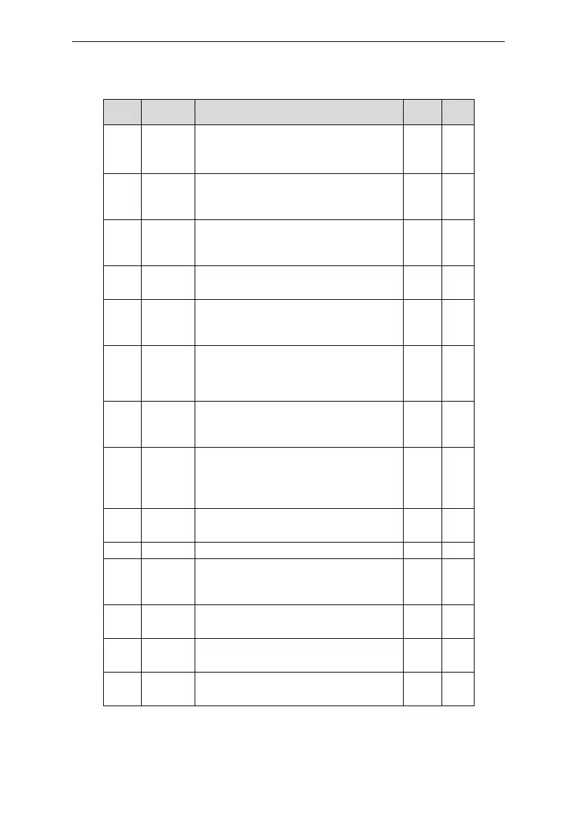
Detailed instruction of parameters
Display current power of the motor.
Setting range: -300.0%~300.0%
(the rated current of the motor)
Display the current output torque of the
inverter.
Range: -250.0~250.0%
The motor
frequency
evaluation
Evaluate the motor rotor frequency on open
loop vector
Range: 0.00~ P00.03
Display current DC bus voltage of the inverter
Range: 0.0~2000.0V
Switch input
terminals
state
Display current Switch input terminals state of
the inverter
Range: 0000~00FF
Switch
output
terminals
state
Display current Switch output terminals state
of the inverter
Range: 0000~000F
Display the adjustment through the keypad of
the inverter.
Range : 0.00Hz~P00.03
Display the torque reference, the percentage
to the current rated torque of the motor.
Setting range: -300.0%~300.0%
(the rated current of the motor)
Display the current linear speed of the inverter.
Range: 0~65535
Display the current counting number of the
inverter.
Range: 0~65535
Display analog AI1 input signal
Range: 0.00~10.00V
Display analog AI2 input signal
Range: 0.00~10.00V
Display analog AI2 input signal
Range: -10.00~10.00V
 Loading...