1-24 Chapter 1: Product introduction
2. Primary/Secondary IDE connector (40-1 pin PRI_IDE1, SEC_IDE1)
These connectors are for Ultra DMA 133/100/66 signal cables. The Ultra
DMA 133/100/66 signal cable has three connectors: a blue connector for the
primary IDE connector on the motherboard, a black connector for an Ultra
DMA 100/66 IDE slave device (optical drive/hard disk drive), and a gray
connector for an Ultra DMA 100/66 IDE master device (hard disk drive). If you
install two hard disk drives, you must congure the second drive as a slave
device by setting its jumper accordingly. Refer to the hard disk documentation
for the jumper settings.
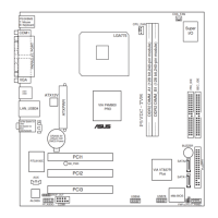
P5VDC-TVM SE
®
P5VDC-TVM SE IDE connectors
NOTE: Orient the red markings
(usually zigzag) on the IDE
ribbon cable to PIN 1.
PIN 1
PRI_IDE1
SEC_IDE1
PIN 1
1. Follow the hard disk drive documentation when setting the device in master
or slave mode.
2. Pin 20 on each IDE connector is removed to match the covered hole on
the UltraATA cable connector. This prevents incorrect orientation when you
connect the cables.
3. The hole near the blue connector on the UltraATA cable is intentional.
 Loading...