10 HIRO Installation Manual GDO-12V1
6.1 Pre-Installation Requirements
NOTE: Planetary chain equipment must be removed from the door prior to
installation of GDO-12V1 HiRo™.
6.1.1 Door Operation
The door must be in good operating condition. The maximum effort to move the
door up or down, from stationary, should not exceed 200 Newtons (44 lb force)
at the bottom rail.
Lift the door to about halfway. When released, the door should stay in place
supported entirely by its springs. Raise and lower the door to check for binding
or sticking.
The door may need to be serviced to meet these requirements – refer to the door
manufacturer’s servicing instructions or contact an authorised dealer.
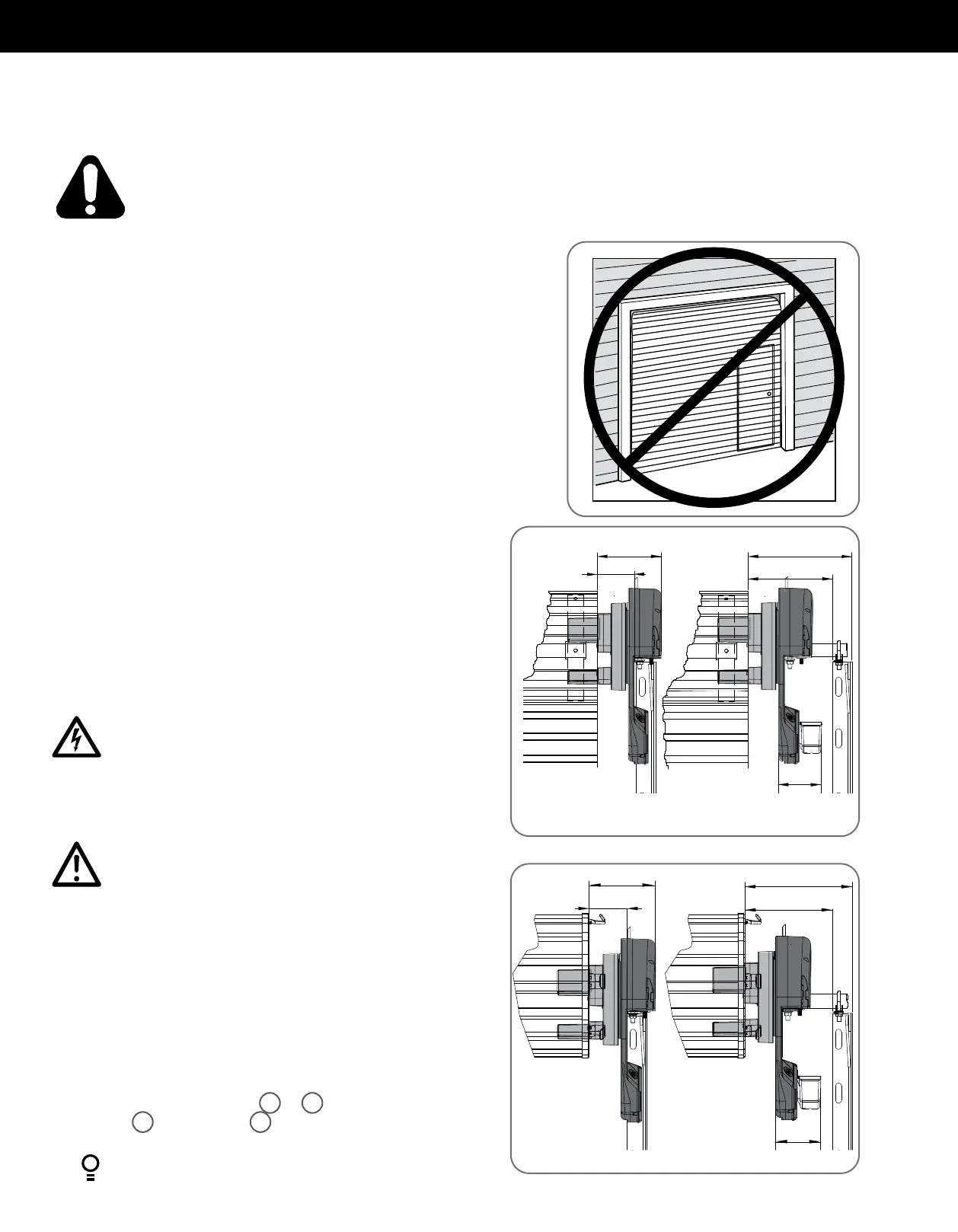
6.1.2 Unsuitable Door Types
The fitting of an opener to doors with removable mullions or doors incorporating
a wicket door is not recommended (Fig. 6.1.1).
6.1.3 Position
The opener can be installed on either the right or left hand side of the door (when
viewed from inside the garage). The opener is factory set for right hand side
installation.
This opener must be installed in a dry position that is protected from the weather.
Moisture or corrosion damage is not covered by the Warranty.
6.1.4 Power Supply
Properly earthed 3 pin single-phase power is required.
Fig 6.1.2
Fig 6.1.3
Fig 6.1.1
8
1
/
4
”
6
1
/
2
”
10”
3
3
/
4
”
Recommended Side roomMinimum Side room
4
1
/
8
”
8
1
/
2
”
6
3
/
4
”
10”
4
3
/
4
”
4
1
/
8
”
Recommended Side roomMinimum Side room
Standard Roller Doors
Windlock Roller Doors
ELECTROCUTION! This operator is not equipped for permanent
wiring. Contact a qualified electrician to install a suitable
receptacle if one is not available.
ÉLECTROCUTION! Ce dispositif d’ouverture n’est pas conçu
pour un câblage permanent. En l’absence de réceptacle
approprié, contactez un électricien qualifié pour en installer un.
CAUTION: Do not connect opener to power source until
instructed to do so.
ATTENTION: Ne branchez pas l’ouvre-porte avant d’y être
autorisé par la notice.
6.1.5 Sideroom
The minimum sideroom required from the edge of the door curtain is 3
3
/
4
” to the
inside of the door bracket, and 6
1
/
2
” to the wall. If the Battery Backup is to be
fitted, at least 8
1
/
4
” to the bracket is required.
Therefore the recommended sideroom from the edge of the door curtain is
130mm to the inside of the door bracket, and 10” to the wall as per diagram (Fig
6.1.2) Please refer to Fig 6.1.3 for Windlock Doors.
NOTE: The door axle diameter must not exceed 1
3
/
8
”.
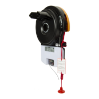
6.1.6 Forks
Attach and secure the three (3) forks
2
or
10
with the six (6) hex serration
head screws
3
to the drive unit
1
(Fig. 6.1.3). All forks must be used and
properly engaged into the drum of the door for the opener to work effectively.
WARNING! It is vital for the safety of persons to follow all instructions. Failure to comply with the installation instructions
and the safety warnings may result in serious personal injury and/or property and remote control opener damage.
AVERTISSEMENT! pour la sécurité des usagers, il est essentiel de suivre toutes les instructions. Le non- respect des
instructions d’installation et des avertissements de sécurité peut causer de graves blessures et/ou endommager
l’appareil et la télécommande.