Centipede
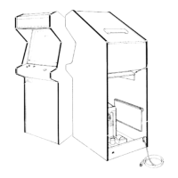
3.
Remove
the two
plug-in
connectors
on
the
speaker.
Remove
the
speaker
from the
wood
board
and
replace it.
4. To
replace
the
fluorescent tube,
remove
the grey
cardboard
locking
tab at
each
end of
the
tube.
Slightly
rotate
the
tube up
or
down,
and
carefully
remove
it
from the
lampholders.
5.
Replace
with a
new tube.
Never
force the
tube
into the
lampholders—you
may
break it,
causing
an
implosion!
of the
circuits; the
diagrams also define inputs and
outputs.
Atari’s
Centipede™ is a
microprocessor-con-
trolled
game. The
microprocessor is mounted on the
game
PCB. The game PCB receives switch
inputs
from the control
panel and coin door. These
inputs
are processed by the
game
PCB
and output to the
monitor, Regulator/Audio
II PCB, loudspeaker, and
control
panel.
6. Also
check
that the
green
ground
wire is
secure-
ly
attached
to
the
large
metal
bracket
and
the
ballast
transformer
behind
the
wood
panel.
If the
lamp is
not
grounded,
it may
not
start.
7. If
you
removed the
light
and
speaker
assembly,
reconnect
the
harness
connector;
then
reinstall
the
assembly.
Replace
the
attraction
panel on
the
front of
the
game.
G.
Game
Operation
With
this
manual
you
received
two large
sheets
that
contain
the
wiring and
schematic
diagrams
for
the
Centipede™
(upright)
game.
Sheet
1,
Side
A,
in-
cludes a
“table of
contents”
that shows the
arrange-
ment
of these
diagrams.
They
explain
the
functions
The Regulator/Audio II
PCB performs two func-
tions:
1)
it regulates
the +10 VDC from the power
supply to + 5
VDC, and
2)
it
amplifies the audio
out-
put
from the game
PCB.
The
+
5
VDC from
the Reg-
ulator/Audio
II PCB provides most logic power to the
game
PCB.
The
audio output from the Regulator/-
Audio II PCB directly
drives
the game
speaker
and
is
controlled by
the volume control, mounted on the
bracket inside the coin door.
The power
supply is the source of all voltages in
the game.
These
voltages
are
protected
by three fus-
es
(F3, F4 and
F5) on
the
power supply chassis. The
primary
winding of the
power
supply
transformer is
protected by the
fuses FI and F2 on the power-sup-
ply
chassis.
Figure 15 illustrates the
distribution of
power
in
this game.
Figure 16 illustrates the distribution
of
signals.
24