Centipede
Signature
Analysis for
Centipede™
Table of
Contents
1. Set-Up for Signature
Analysis
2.
Checking
Address Lines
3. Checking Address
Decoder
4. Checking ROM and
Data Lines
5.
Checking
Horizontal Sync
6.
Checking
Vertical Sync
1.
Set-Up
for Signature
Analysis
A. CAT Box Preliminary
Set-Up
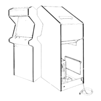
1. Remove:
•
The electrical power from
the game.
•
The wiring harness
from the
game PCB.
•
The game PCB from
the cabinet.
•
The MPU chip
C2
from
the
game PCB.
2. Connect:
•
The extender
cables
to
the
game
PCB
and
the wiring
harness.
•
Pins
37
to
39
on the
MPU socket
with
a
piece of 28 AWG wire.
•
The CAT Box flex cable
to
the
game PCB
test
edge
connector.
B. Signature
Analysis Procedure
1.
Connect
the three BNC to E-Z clip cables
(sup-
plied
with
the CAT Box) to the SIGNATURE
ANALYSIS CONTROL START, STOP,
and
CLOCK
jacks
on the
CAT
Box.
2.
Attach the three black E-Z clips to
a
ground loop
on the
Centipede™ game PCB.
3.
Attach the CAT Box data
probe
to
the DATA jack
on the CAT Box.
4.
The colored E-Z
clips on the cables will
be
moved about
for each group of signatures to be
taken.
The
set-up
for each group of signatures is
located on the
schematic sheet near the device
to be
checked.
The signatures are located on or
near the
signal point on the schematic.
5.
Set the
CAT Box
switches
as follows:
a. TESTER MODE:
SIG
b.
TESTER
SELF-TEST:
OFF
c. PULSE
MODE:
LATCHED
d. START: As
indicated
e. STOP:
As indicated
f.
CLOCK: As
indicated
6. Power
up
the
game
board
and the
CAT
Box.
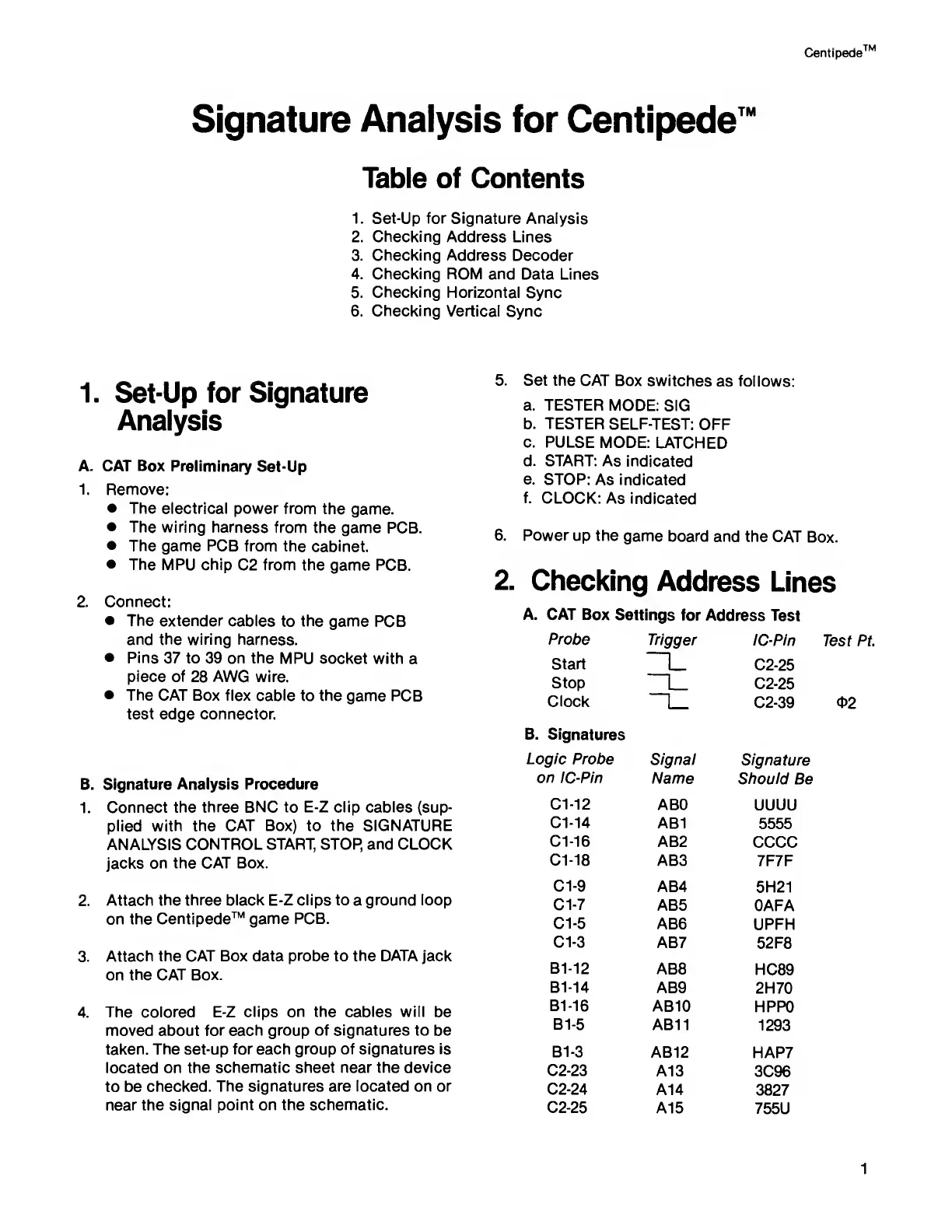
2.
Checking
Address
Lines
A.
CAT Box
Settings for
Address
Test
Probe
Trigger
IC-Pin
Start
|_ C2-25
Stop
L
C2-25
Clock
C2-39
B.
Signatures
Logic
Probe
Signal
Signature
on
IC-Pin
Name
Should
Be
C1-12 ABO
UUUU
C1-14
AB1
5555
C1-16
AB2
CCCC
C1-18
AB3
7F7F
C1-9
AB4
5H21
Cl -7
AB5 OAFA
Cl
-5
AB6 UPFH
Cl
-3
AB7
52F8
B1-12
AB8
HC89
B1-14
AB9
2H70
B1-16
AB10
HPPO
B1-5
AB11
1293
B1-3
AB12
HAP7
C2-23
A13
3C96
C2-24
A14
3827
C2-25
A15
755U
1