Quick start manual - F5200
MR-F5200B-U Quick start manual ATEQ F5200 Page 5/17
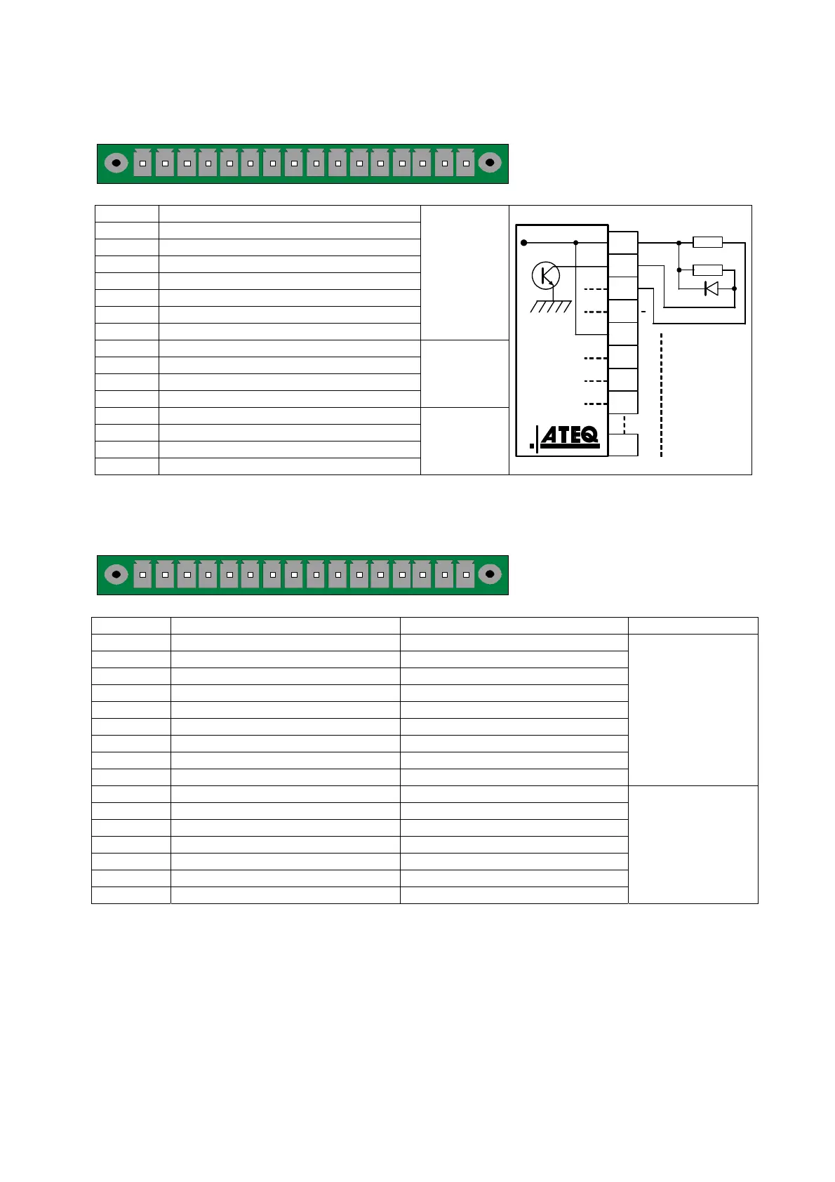
2.4. J1 CONNECTOR OUTPUT CODES / ANALOGUES
1 2 3 4 5 6 7 8 9 10111213141516
Output codes / Analog
outputs / temperature sensor.
PIN 1 COMMON (outputs 1, 2, 3) + 24 V DC
PIN 2 Output n°1, open collector
PIN 3 Output n°2, open collector
PIN 4 Output n°3, open collector
PIN 5 COMMON (outputs 4, 5, 6) + 24 V DC
PIN 6 Output n°4, open collector
PIN 7 Output n°5, open collector
PIN 8 Output n°6, open collector
OUTPUT
CODES
24V DC
100mA Max
Outputs
PIN 9 12V Sensor power supply
PIN 10 0V Sensor power supply
PIN 11 SENSOR n°1 input
PIN 12 SENSOR n°2 input
TEMP°
SENSORS
PIN 13 Analogue outputs n°1
PIN 14 COMMON (analogue output 1)
PIN 15 Analogue output n°2
PIN 16 COMMON (analogue output 2)
ANALOGUE
OUTPUTS
24 V DC
8
7
6
5
4
3
2
1
0,1 A max
Charge / Load
Obligatory
diode for an
inductive load.
2.5. J3 CONNECTOR I/O ALL OR NOTHING
1 2 3 4 5 6 7 8 9 10111213141516
Inputs / All or nothing outputs.
Pin Standard mode Compact mode
1 Input 1 Reset Input 1 Reset
2 Common (+ 24 V) Common (+ 24 V)
3 Input 2 START Input 2 START
4 Common (+ 24 V) Common (+ 24 V)
5 Input 3 Program selection Input 3 Program selection
6 Input 4 Program selection Input 4 Program selection
7 Input 5 Program selection Input 5 Program selection
8 Input 6 Program selection Input 6 Program selection
9 Input 7 Program selection Input 7 Program selection
INPUTS
(Activating by
24 V DC)
Common
+ 24 V = 0,3 A
maxi
10 Floating common output Floating common output
11 Output 1 Pass part Output 1Pass part cycle 1
12 Output 2 Test error Output 2 Fail part cycle 1 + alarm
13 Output 3 Reference error Output 3 Pass part cycle 2
14 Output 4 Alarm Output 2 Fail part cycle 2 + alarm
15 Output 5 End of cycle Output 5 End of cycle
16 0 V 0 V
DRY CONTACT
OUTPUTS
60V AC / DC Max
200mA Max
The compact mode is a software function which is activated in the CONFIGURATION /
CHANGE I/O / OUTPUT menu.
2.5.1. J3 Connector program selection
The various test programs can be selected individually depending on the inputs
combination of this connector.