ATI Q46H/85 PAA System Part 2 – Analyzer Mounting
12
O&M Manual
Rev F (8/17)
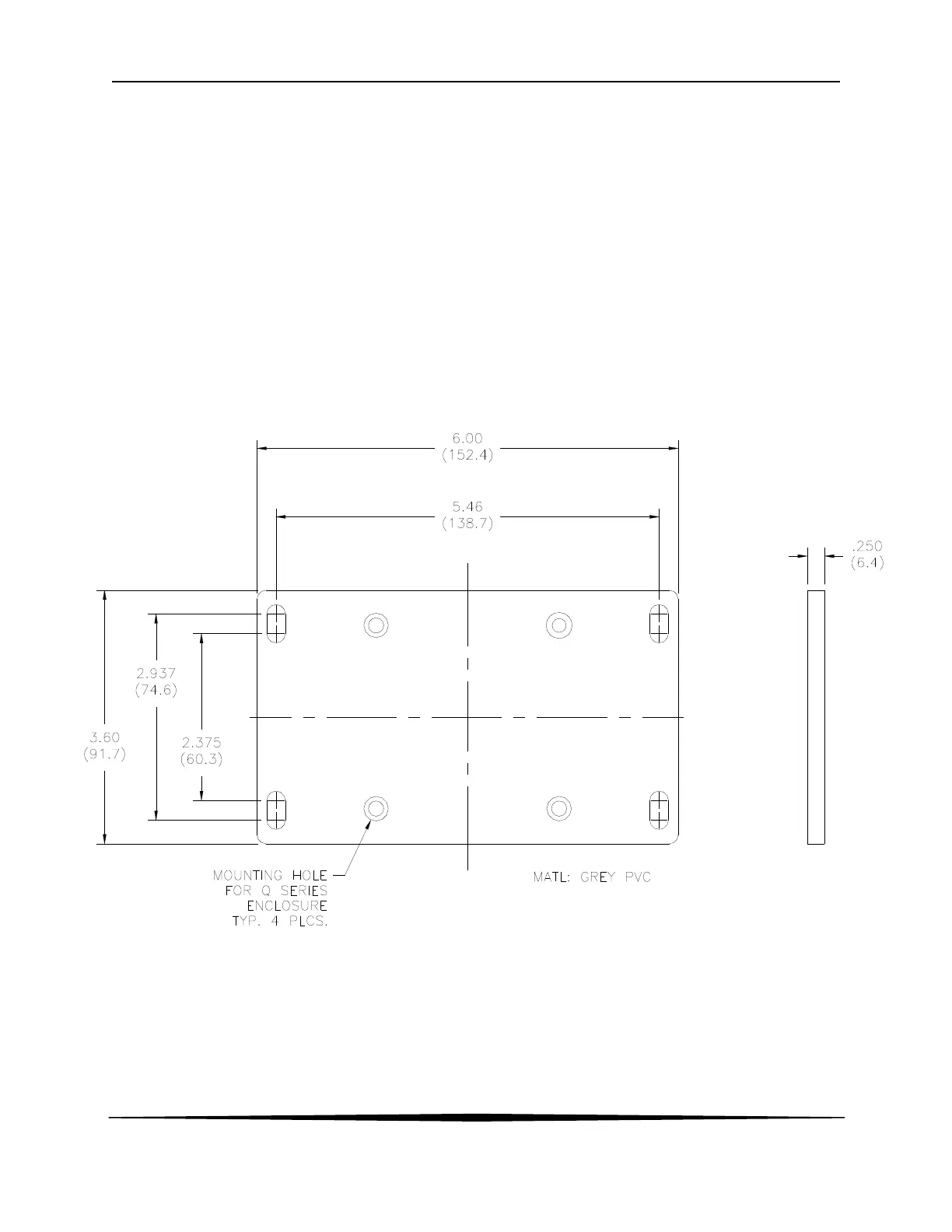
2.2 Wall or Pipe Mount
A PVC mounting bracket with attachment screws is supplied with each transmitter as shown in
Figure 5. The multi-purpose bracket is attached to the rear of the enclosure using the four flat
head screws. The instrument is then attached to the wall using the four outer mounting holes in
the bracket. These holes are slotted to accommodate two sizes of u-bolt that may be used to
pipe mount the unit. Slots will accommodate u-bolts designed for 1½ “ or 2” pipe. The actual
center to center dimensions for the u-bolts are shown in the drawing. Note that these slots are for
u-bolts with ¼-20 threads. The 1½” pipe u-bolt (2” I.D. clearance) is available from ATI in type
304 stainless steel under part number (47-0005).
Figure 5 - Wall or Pipe mount Bracket