15
O&M Manual
Rev F (8/17)
Part 3 – Sensor/Flowcell Mounting
3.1 General
Select a location within the maximum sensor cable length for mounting of the sensor flow cell.
3.2 Constant-Head Flowcell
PAA sensors are best used in a constant-head overflow chamber because variations in sample
flow rate and pressure can cause unstable readings. When monitoring low concentrations (below
0.5 PPM), this method should always be used. Mechanical installation of the flow cell requires
that it be mounted to a wall or other convenient flat surface. Alternatively, the mounting holes on
the plate will accommodate a 2" U-bolt for mounting the plate to a 2" pipe. Figure 9 shows the
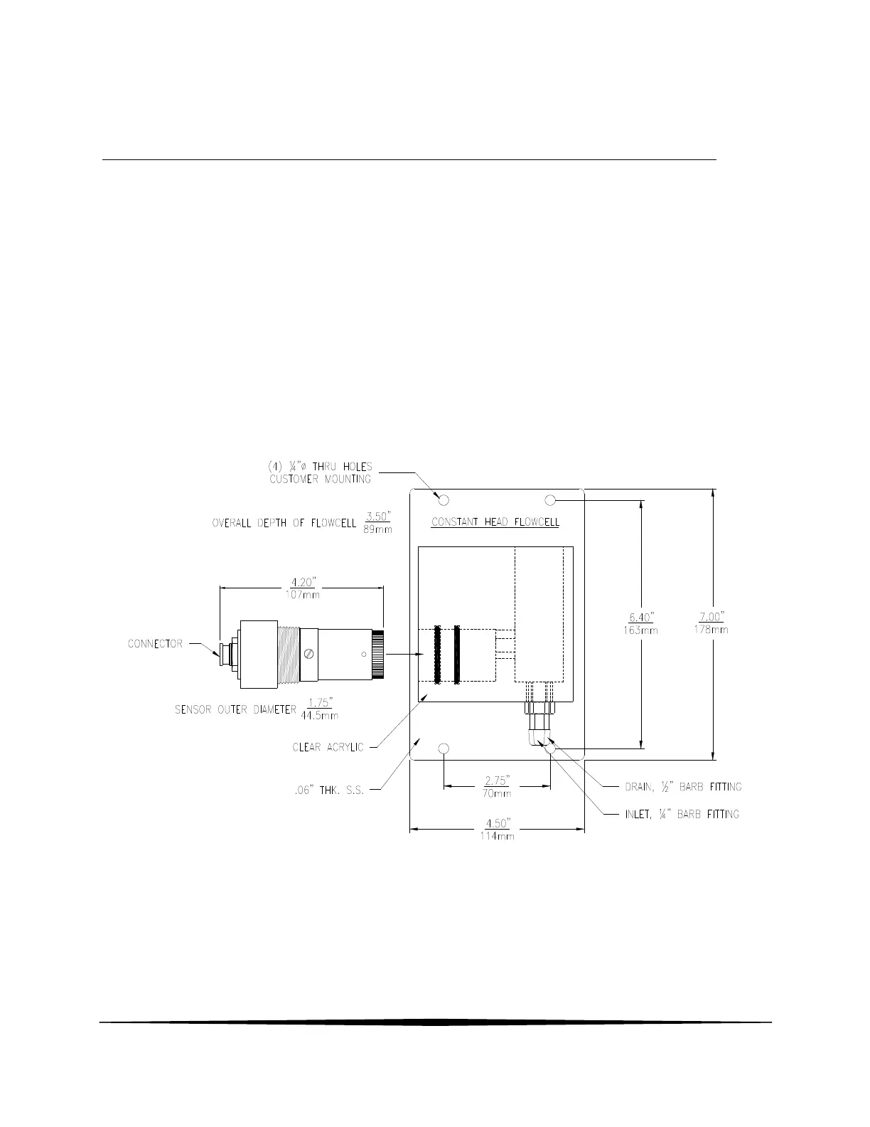
dimensions and mounting hole locations for the flow cell. Be sure to allow enough clearance on
the left side of the flow cell for insertion and removal of the sensor. About 12 inches clearance is
recommended.
Figure 9 - Constant Head Flowcell Details
Once mounted, inlet and drain connections must be made. The flow cell contains a 1/8" MNPT
inlet connection and a 3/8" MNPT drain connection. Hose barbs for the inlet and drain
connections are supplied with the flow cell for use with flexible tubing. The inlet hose barb is
used with ¼" I.D. tubing and the drain hose barb is used with ½" I.D. tubing.