ATI Q46H/85 PAA System Part 2 – Analyzer Mounting
7
O&M Manual
Rev F (8/17)
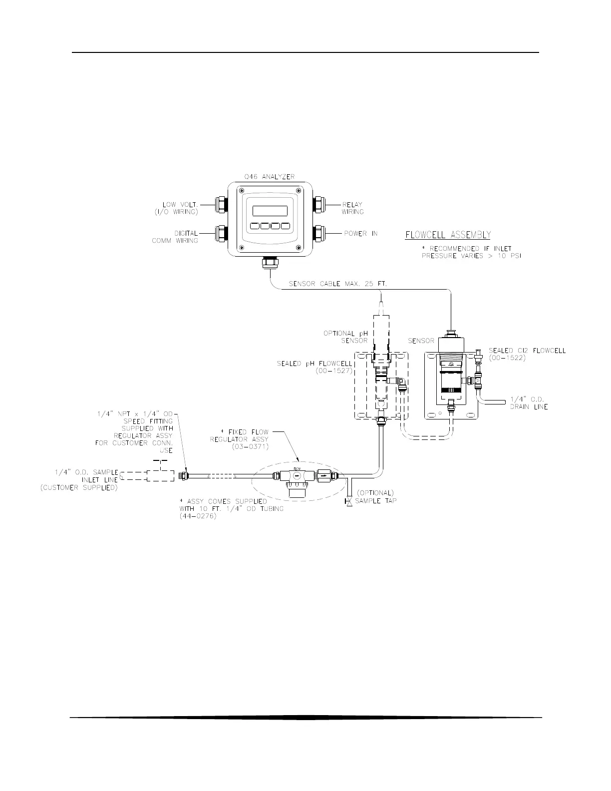
Figure 3 below shows an installation using a (00-1522) sealed flowcell for the PAA sensor and a (00-
1527) sealed flowcell for the pH sensor. This type of installation requires careful flow control. We
recommend the use of our (03-0371) flow control assembly when using sealed flowcells. This assembly
consists of an in-line filter and a fixed-flow regulator which will maintain a constant 400 cc/min flowrate
through the system. This flow will be maintained so long as inlet pressures are between 5 and 125 PSIG.
The in-line filter is used mainly to protect the flow control element against larger particles that might cause
plugging of the device.
Figure 3 - Sealed Flowcell Assemblies w/Flow Control