ATI Q46H/85 PAA System Part 4 – Electrical Installation
21
O&M Manual
Rev F (8/17)
4.3 Relay Connection
Three SPDT relays are provided on the power supply board. None of the relay contacts are
powered. The user must supply the proper power to the contacts. For applications that require
the same switched operating voltage as the Q46 (115 or 230 V), power may be jumpered from
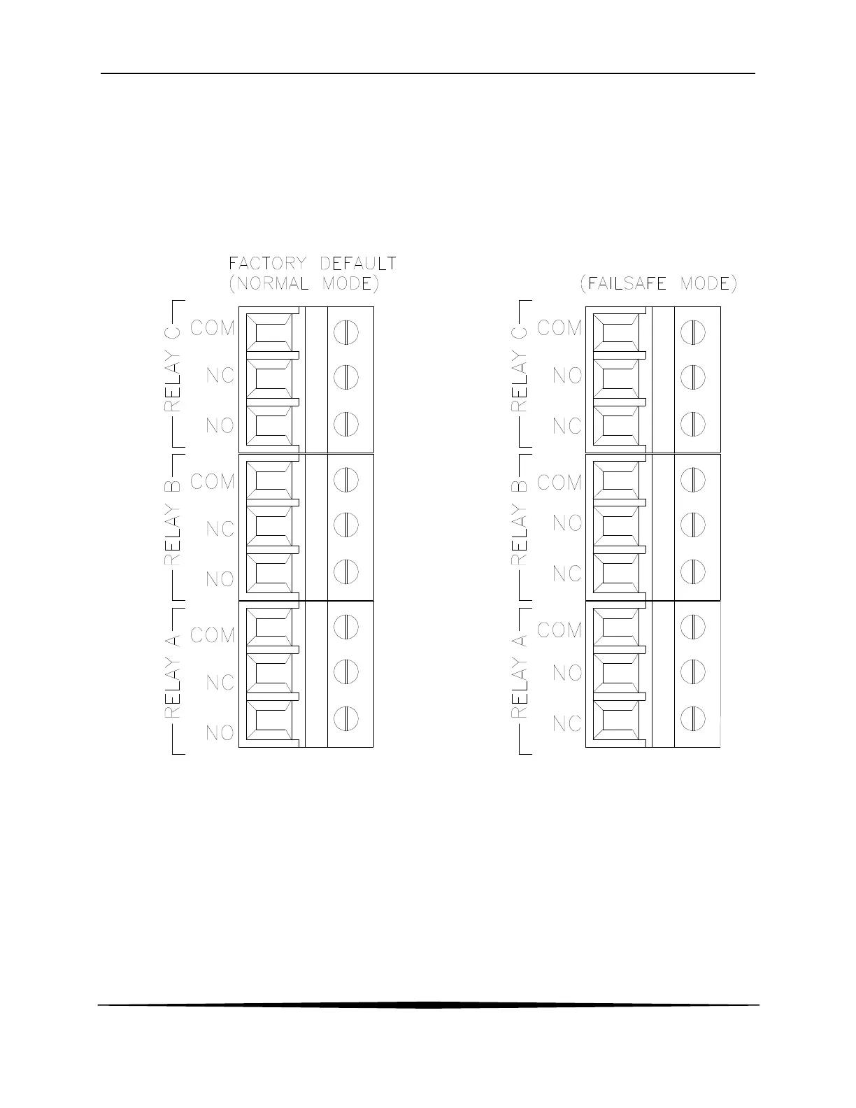
the power input terminals at TB7. Relay wiring is connected at TB4, TB5, and TB6 as shown
below. Note that the relay contact markings are shown in the NORMAL mode. Programming a
relay for “Failsafe” operation reverses the NO and NC positions in this diagram
Figure 14.
Figure 14 - Optional Relay Board Wiring



 To Next Page