ATI Q46H/85 PAA System Part 4 – Electrical Installation
24
O&M Manual
Rev F (8/17)
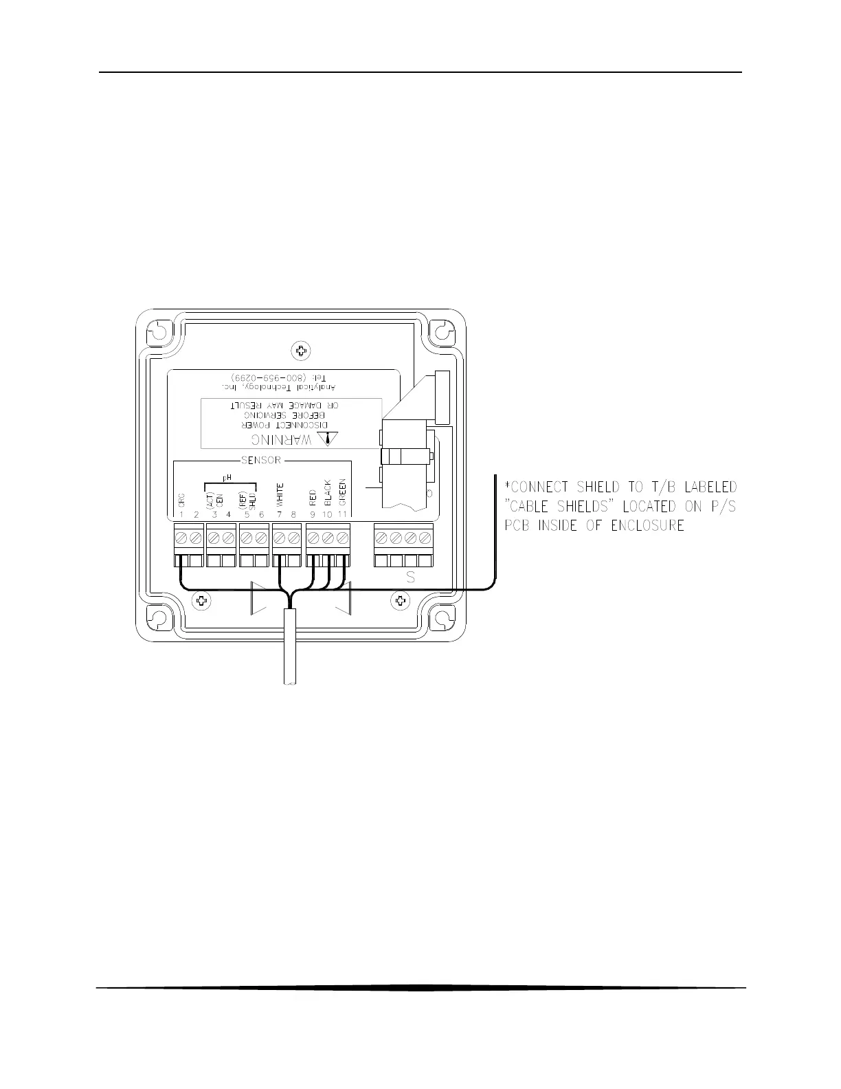
4.5 Sensor Wiring
The sensor cable can be quickly connected to the Q46 terminal strip by matching the wire colors
on the cable to the color designations on the label in the monitor. A junction box is also available
to provide a break point for long sensor cable runs. Route signal cable away from AC power
lines, adjustable frequency drives, motors, or other noisy electrical signal lines. Do not run
sensor or signal cables in conduit that contains AC power lines or motor leads.
Note: If sensor is experiencing Low-Slope or Low-Output conditions, due
To poor Earth Ground Connections, move the Shield connection
from P/S board to alternate location on lid, where indicated with an
“S”.
Figure 18 - Sensor Wiring