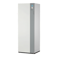
2.6.4 Creating the arings
- Cut the pipe to an appropriate length with a pipe-cutter
without deforming it.
- Carefully deburr it, holding the pipe towards the bottom
to avoid introducing lings into the pipe.
- Remove the ared connection nut situated on the
valve to be connected and slip the pipe into the nut.
- Proceed to are, letting the pipe overow the aring
tool.
- After aring, check the condition of the working radius
(L). This must not show any scratch or trace of any
fracturing. Also check the dimension (B).
Flaring tool
Hose
Flare
nut
B
L
C
ø hose Dimensions in mm
L B
0
/
-0,4
C
6,35 (1/4") 1,8 to 2 9,1 17
9,52 (3/8") 2,5 to 2,7 13,2 22
12,7 (1/2") 2,6 to 2,9 16,6 26
15,88 (5/8") 2,9 to 3,1 19,7 29
4
3
B
3
B
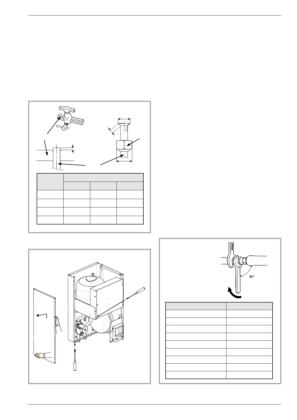
gure 17 - Removing the left-hand panel
2.6.5 Shaping the refrigeration pipes
The refrigeration pipes must be shaped only on a
bending machine or with a bending spring in order to
avoid any risk of crushing or breaking them.
" Warning !
• Remove the insulation material locally to bend the
pipes.
• Do not bend the copper to any angle over 90°.
• Never bend pipes more than 3 times in the same
position otherwise traces of fracturing may appear
(from strain-hardening the metal).
2.6.6 Connecting the ared connections
" Take particular care positioning the tube
opposite its connector so as not to risk damaging
the threads. A carefully aligned connector can
be tted easily by hand without much force
being required.
" The refrigeration circuit is very sensitive to dust
and humidity: check that the area around the
connection is clean and dry before removing the
plugs protecting the refrigeration connectors.
- Depending on the case, connect an adapter (reducer)
1/4''- 3/8'' or 1/2''- 5/8' (see gure 18).
- Remove the plugs from the pipes and the refrigeration
connections.
- Present the pipe to the ared connector and screw the
nut by hand while holding the connector with a wrench
until contact.
- Warning! Do not position the gas tube in front of the
circulation pump cleaning screw.
- Comply with the indicated tightening torques.
gure 18 - Tightening torque
Designation Tightening torque
Flare nut 6,35 mm (1/4") 14 to 18 Nm
Flare nut 9,52 mm (3/8") 33 to 42 Nm
Flare nut 12,7 mm (1/2") 50 to 62 Nm
Flare nut 15,88 mm (5/8") 63 to 77 Nm
Plug (A) 3/8", 1/4" 20 to 25 Nm
Plug (A) 1/2" 25 to 30 Nm
Plug (A) 5/8" 30 to 35 Nm
Plug (B) 3/8", 5/8" 10 to 12 Nm
Plug (B) 1/2", 1/4" 12,5 to 16 Nm
Holding wrench
Torque wrench
Installation and operation manual "1397 - EN" - 17 -
Heat pump split single service alféa Evolution