POWER FOCUS 6000 EN Installation
© Atlas Copco Industrial Technique AB - 9836 6528 01
11
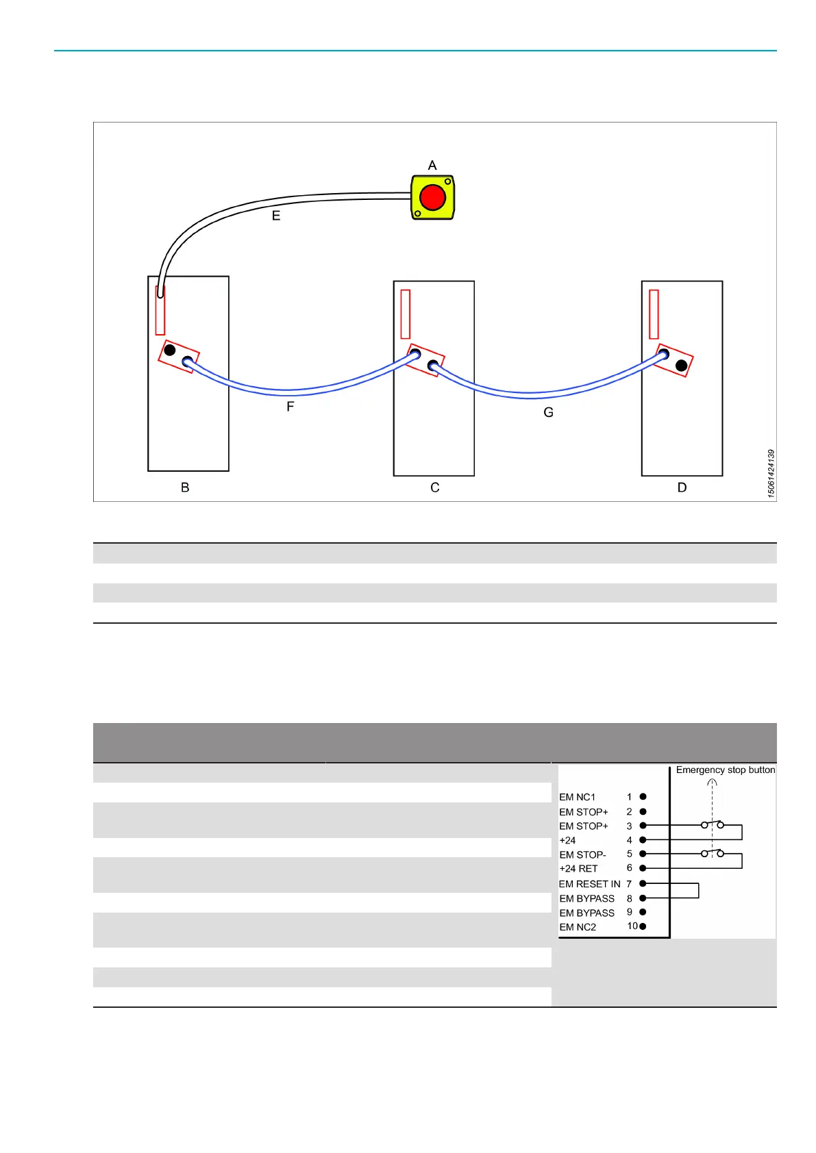
Multiple Controllers with an EM Stop Button
Connection schematics for an emergency stop button in a multiple controller configuration.
A Emergency stop button
B, C, D Controllers
E Emergency stop button cable
F, G Emergency stop I/O cables
The pin configuration differs depending on the controller location within the EM Stop chain.
First controller with an EM Stop button connected
EM Stop button connector: Phoenix, 10-pin headers, 3.5 mm pitch
Use the following pin configuration:
Pin Use
1 Do not use
2 Do not use
3 Attach an emergency button be-
tween pin 3 and pin 4
4 See pin 3
5 Attach an emergency button be-
tween pin 5 and pin 6
6 See pin 5
7 Connect a jumper between pin 7
and pin 8
8 See pin 7
9 Do not use
10 Do not use
Controllers between first and last
EM Stop I/O cable connector: Phoenix, 10-pin
Remove plug or use the following pin configuration:
 Loading...