Installation EN POWER FOCUS 6000
8
© Atlas Copco Industrial Technique AB - 9836 6528 01
8. Residual-current device (RCBO)
9. Digital input
10. Digital output
11. I/O bus
12. Factory Ethernet port
13. Anybus CC
14. Power connector
Installation Instructions
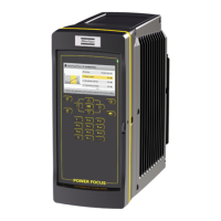
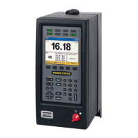
Installing the Controller
The controller must be positioned so that the power switch is easily accessible.
For maximum tool performance, make sure that the controller is installed so that free airflow is pro-
vided. This improves the cooling of the controller.
1. Attach the mounting plate to a wall or to a steel plate, using three M6 screws. If attaching to a wall,
use the correct wall bracket (plug and screw). If attaching to a steel plate, make sure that the steel
plate is at least 2 mm thick.
2. Attach the controller to the mounting plate by tilting the controller and guiding the top flange of the
mounting plate into the slot on the back of the controller. Lower the controller to engage the locking
mechanism.
3. Install the retainer strap between the wall and the cable cover.
4. Open the front access door of the controller.
5. Connect the power cable to the power connector.
6. Place the IAM in its socket on the back of the front access door.
7. Make sure that the RCBO (residual-current device) is switched on.
8. Close the front access door.
9. Connect the tool cable to its socket on the bottom part of the controller.
10. Connect the power cable to a power supply.
11. Turn the power switch on.
An optional, threaded grounding point is available on the lower backside of the controller. The
grounding point accepts a M4 threaded screw. The additional grounding does not replace the ground-
ing from the wall socket.
Configuring Remote Start for Single or Multiple Controllers
The switch for remote start is found on the connector board located behind the front access door.
Whenever enabling remote start you must, for safety reasons, implement an emergency stop solution.
When using portable hand-held or portable hand-guided tools (such as tools used with torque reac-
tion devices or dual trigger), remote start must be disabled by setting the switch on the controller to
OFF. This is done to make it impossible to override the safety function within the tools.
Emergency Stop
The supply disconnecting device may serve as an emergency stop when it is readily accessible to the op-
erator and it is of the type described in EN 60204-1:2006, 5.3.2 a), b), c) or d). When intended for such
use, the supply disconnecting device shall be colored red and have a yellow background. (Ref. EN
60204-1:2006, 10.7.5).
 Loading...
