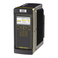
POWER FOCUS 6000 EN Installation
© Atlas Copco Industrial Technique AB - 9836 6528 01
9
The POWER FOCUS 6000 provides an infrastructure to build an Emergency Stop function with redundant
breaking according to EN ISO 13849-1 category 3 PL d. The Emergency Stop function must be used
when using remote start functionality.
The Emergency Stop functionality can be used with a supply-disconnecting device (such as an Emer-
gency Stop button). When the Emergency Stop button is activated, it breaks the supply voltage to the con-
troller.
A diagnose of the system is run automatically at the start of the controller. This is done both after an emer-
gency stop and at a normal start.
The Emergency Stop function is used with either a single controller or up to 10 controllers in a single
emergency stop chain. In a multiple controller configuration, the Emergency Stop signal is distributed from
the first controller to all interconnected controllers using the I/O bus interface. The last controller in the
chain returns a feedback signal to indicate that all controllers have received the Emergency Stop signal.
The event Emergency Stop is displayed.
For the Emergency Stop there is a 24V DC output through the Emergency Stop interface on the connector
panel.
Cabling
EM Stop button cables
Single/Multiple controllers Dimension Maximum length
Single 0.7 mm
2
cable 400 meters
Multiple 1.5 mm
2
cable 50 meters
I/O Cables
For connecting multiple controllers with I/O cables distributing the emergency stop signal, use the maxi-
mum length according to the following table:
AWG 22 cable Maximum total length
4 controllers 200 meters
5 controllers 140 meters
6 controllers 100 meters
8 controllers 70 meters
10 controllers 50 meters
Pin Configurations for Emergency Stop
The POWER FOCUS 6000 has an external EM Stop interface and an I/O bus on the connector board that
is located behind the front access door.
The pin configuration is different for single controller solutions and for multiple controller solutions. For sin-
gle controller solutions, the pin configuration depends on whether or not an EM Stop button is connected
to the controller.
Single Controller with EM Stop Button
Connector: Phoenix, 10-pin headers, 3.5 mm pitch
Use the following pin configuration:
 Loading...