User guide EN TPS Control
6
© Atlas Copco Industrial Technique AB - 9836 5819 01
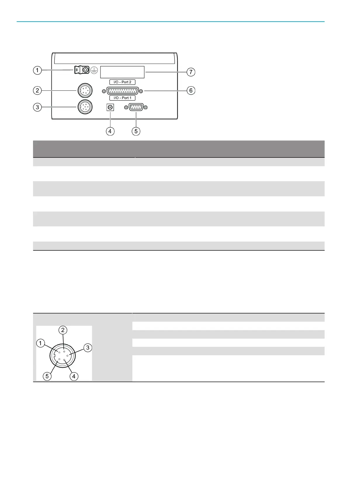
Connections
Number Part Description
1 Ground For flash plug for ground connection.
2 Analogue encoder inter-
face
For 5-pin flange socket (Binder, Series 680) connected to the analogue
encoder on the torque arm
3 SSI encoder interface For 7-pin flange socket (binder, Series 680) connected to the angle en-
coder on the torque arm
4 Power supply For connection to the 24 VDC power supply unit, 5.5 mm socket with
2.1 mm center pin
5 RS-232C serial interface For 9-pin Sub-D socket connected to the external equipment, for exam-
ple Barcode scanner or PC
6 Digital I/O connection I/O
Port 1
For 25-pin Sub-D socket connected to the tool controller.
7 I/O Port 2 Not used.
Ground connection
A 6.3 mm flash plug used for ground connection. This connection must be linked to the protective ground
for safe operation of the TPS Control.
Analogue encoder connection
Interface with a 5-pole connection for an analogue encoder. Use a 5-pole pin plug from the Binder 680 Se-
ries. This encoder can either be of a lineary or angle type using analogue 0-10 V.
PIN Signal
1 24 V Supply
2 24 V GND
3 Analogue input
4 Analogue GND
5 Not connected
SSI encoder connection
SSI interface with a 7-pole connection for the SSI encoder. Use a 7-pole pin plug from the Binder 680 Se-
ries.
 Loading...