AT90S4414/8515
34
•
Bit 3 - CTC1: Clear Timer/Counter1 on Compare Match
When the CTC1 control bit is set (one), the Timer/Counter1 is reset to $0000 in the clock cycle after a compareA match.
If the CTC1 control bit is cleared, Timer/Counter1 continues counting and is unaffected by a compare match. Since the
compare match is detected in the CPU clock cycle following the match, this function will behave differently when a prescal-
ing higher than 1 is used for the timer. When a prescaling of 1 is used, and the compareA register is set to C, the timer will
count as follows if CTC1 is set:
... | C-2 | C-1 | C | 0 | 1 | ...
When the prescaler is set to divide by 8, the timer will count like this:
... | C-2, C-2, C-2, C-2, C-2, C-2, C-2, C-2 | C-1, C-1, C-1, C-1, C-1, C-1, C-1, C-1 | C, 0, 0, 0, 0, 0, 0, 0 | ...
In PWM mode, this bit has no effect.
•
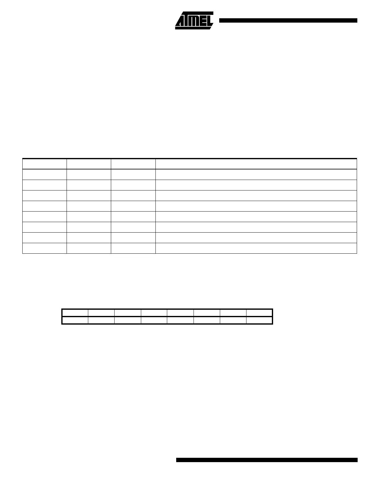
Bits 2,1,0 - CS12, CS11, CS10: Clock Select1, bit 2,1 and 0
The Clock Select1 bits 2,1 and 0 define the prescaling source of Timer/Counter1.
The Stop condition provides a Timer Enable/Disable function. The CK down divided modes are scaled directly from the CK
oscillator clock. If the external pin modes are used for Timer/Counter1, transitions on PB1/(T1) will clock the counter even if
the pin is configured as an output. This feature can give the user SW control of the counting.
Timer/Counter1 - TCNT1H AND TCNT1L
This 16-bit register contains the prescaled value of the 16-bit Timer/Counter1. To ensure that both the high and low bytes
are read and written simultaneously when the CPU accesses these registers, the access is performed using an 8-bit
temporary register (TEMP). This temporary register is also used when accessing OCR1A, OCR1B and ICR1. If the main
program and also interrupt routines perform access to registers using TEMP, interrupts must be disabled during access
from the main program (and from interrupt routines if interrupts are allowed from within interrupt routines).
• TCNT1 Timer/Counter1 Write:
When the CPU writes to the high byte TCNT1H, the written data is placed in the TEMP register. Next, when the CPU
writes the low byte TCNT1L, this byte of data is combined with the byte data in the TEMP register, and all 16 bits are
written to the TCNT1 Timer/Counter1 register simultaneously. Consequently, the high byte TCNT1H must be accessed
first for a full 16-bit register write operation.
Table 11. Clock 1 Prescale Select
CS12 CS11 CS10 Description
0 0 0 Stop, the Timer/Counter1 is stopped.
001CK
010CK/8
011CK/64
100CK/256
101CK/1024
1 1 0 External Pin T1, falling edge
1 1 1 External Pin T1, rising edge
Bit 151413121110 9 8
$2D ($4D) MSB TCNT1H
$2C ($4C) LSB TCNT1L
76543210
Read/Write R/W R/W R/W R/W R/W R/W R/W R/W
R/W R/W R/W R/W R/W R/W R/W R/W
Initial value 0 0 0 0 0 0 0 0
00000000

 Loading...


