41
1. Turn on the laser enable;
2. The LA-ON-pin of the controller is connected to the metal welding
workpiece through a wire (refer to the device wiring chapter);
3. The tip of the gun contacts the metal welding workpiece;
4. Press the light control switch of the welding gun;
5. The device currently has no alarms.
In the case that the laser can work normally, the light cannot be emitted
when one of the above 5 conditions is not met.
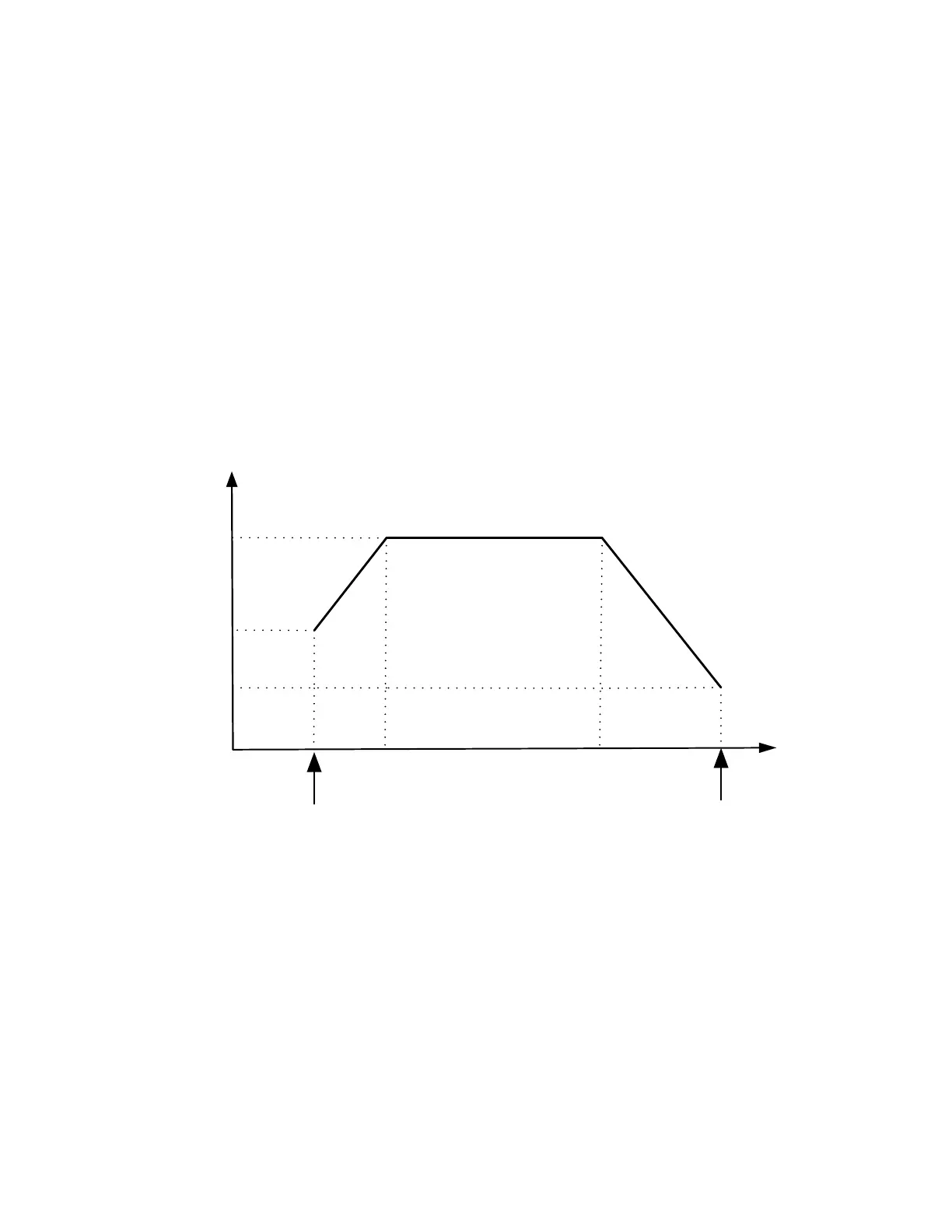
The process of power change during light emission is shown in the following
figure.