page 4 – 2
R-55e / July 2004
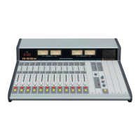
OUTPUT MODULE
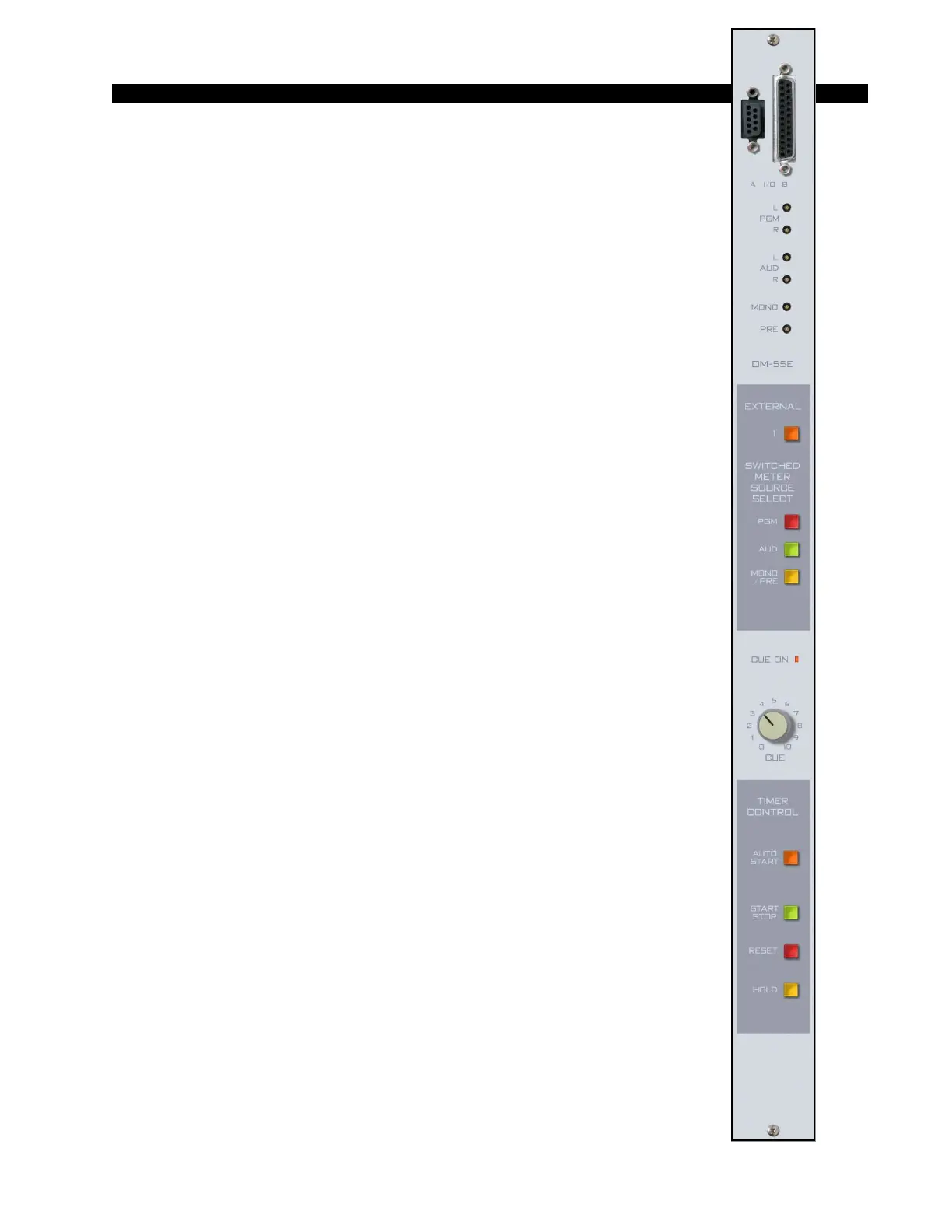
Output Module (OM-55e)
Module Overview
The master output module handles the console’s Program, Audi-
tion, and Mono/Mix-Minus outputs. All outputs are calibrated with
recessed front panel multi-turn trimpots.
The R-55e console has two pairs of left-right VU meters, PGM and
SWT (switched), except for the R-55e-8 (12 position frame), which has
only the SWT meter pair. The meters are located on the console’s
meterbridge. The switched meter follows the SELECT switching,
allowing the console operator to meter PGM, AUD, MONO and PRE,
and an external stereo line signal (analog, +4dBu balanced), which may
be brought into the module on its DB-25 connector.
The OM-55e module houses the master Cue LED. Whenever Cue
is activated anywhere on the console this LED will illuminate and the
CUE signal will automatically appear on the switched VU meter pair.
When cue is de-activated, the switched meter pair goes back to its
previously selected signal.
The CUE master level control sets the level of the console’s cue
signal.
Whenever CUE is activated elsewhere on the console (stereo line inputs,
the superphone module, or for studio talkback) its signal will appear at the
console’s built-in cue speaker mounted in the meterbridge. Depending on how
the CRS-55e module has been programmed, cue can also interrupt the control
room monitor speakers. The way Cue interrupts the control room/studio
outputs is determined by PCB-mounted dipswitch. See “Cue Interrupt” on page
5-3.
The OM-55e module also generates the console’s monitor signals,
which feed the Control Room and Studio modules.
At the bottom of module are the timer control buttons (the timer
display is mounted in the righthand end of the console meterbridge):
AUTO START – enables timer restart functions from programmed input
modules’ ON buttons.
START/STOP - halts the timer, holds the last count, and then restarts and
accumulates the count when depressed again.
RESET - return to zero (if the timer is stopped it will hold at zero; if it is
running it will reset to zero and immediately begin counting up).
HOLD – when held down freezes the timer display (the counter keeps on
going); when released the display catches up to the current count.
All user wiring to and from the OM-55e module takes place at
DB-25 and DB-9 multi-pin connectors mounted on top of the module
and located underneath the hinged meterbridge. All analog audio is
+4dBu balanced. Pinout drawing on page 4-5 shows all wiring connec-
tions at a glance.
R-55e / Dec 2004