page 5 – 4
R-55e / July 2004
CONTROL ROOM MODULE
Hook-Ups
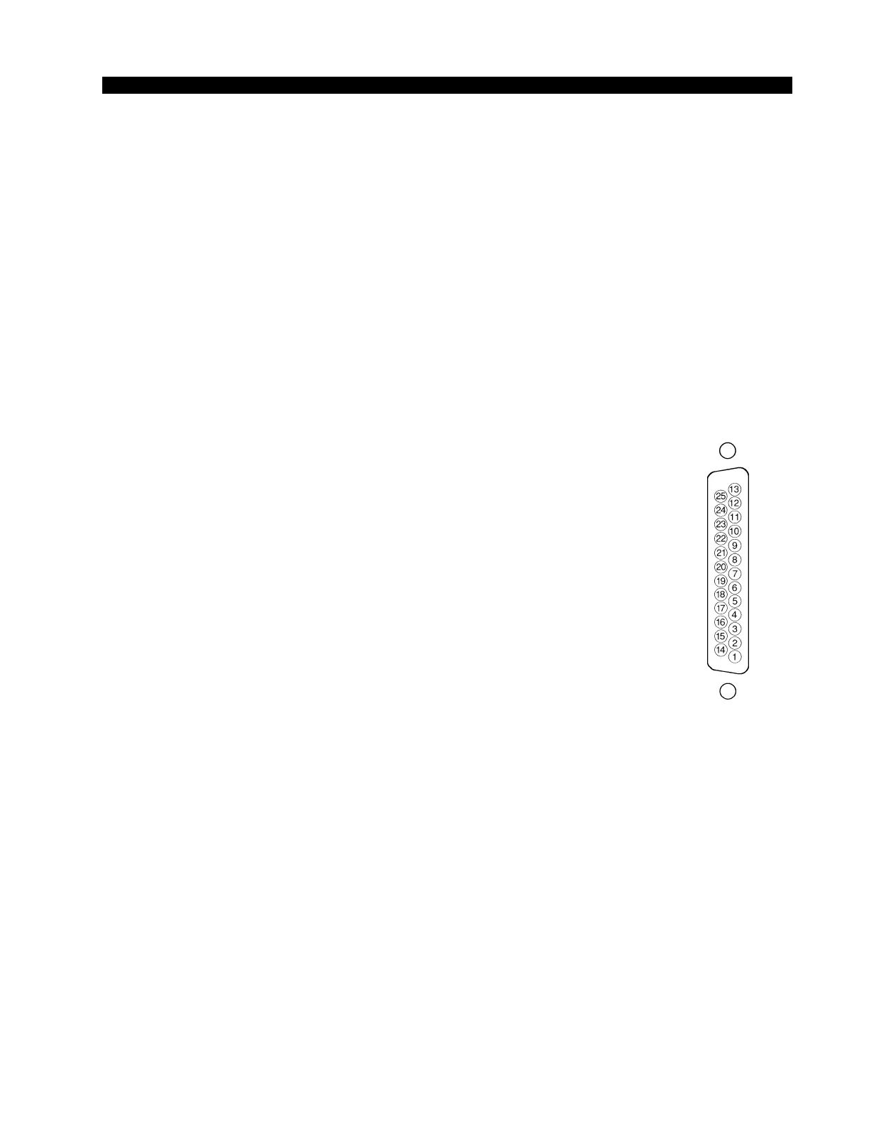
As stated before, all user wiring to and from the CRS-55e module takes
place at the two DB-25 multi-pin connectors mounted at the top of the
module.
Left DB-25 “A” Connector — Audio
Handles module’s External 2 Stereo inputs and studio pre, headphone
pre, and monitor pre outputs. All audio signals are analog stereo, +4dBu
balanced.
Pin 25 – Ext 2 Lt In SH
Pin 24 – Ext 2 Lt In HI
Pin 12 – Ext 2 Lt In LO
Pin 11 – Ext 2 Rt In SH
Pin 10 – Ext 2 Rt In HI
Pin 23 – Ext 2 Rt In LO
Pin 22 – ST Pre Lt Out SH
Pin 21 – ST Pre Lt Out HI
Pin 9 – ST Pre Lt Out LO
Pin 8 – ST Pre Rt Out SH
Pin 7 – ST Pre Rt Out HI
Pin 20 – ST Pre Rt Out LO
Pin 19 – HDPN Pre Lt Out SH
Pin 18 – HDPN Pre Lt Out HI
Pin 6 – HDPN Pre Lt Out LO
Pin 5 – HDPN Pre Rt Out SH
Pin 4 – HDPN Pre Rt Out HI
Pin 17 – HDPN Pre Rt Out LO
Pin 16 – MON Pre Lt Out SH
Pin 15 – MON Pre Lt Out HI
Pin 3 – MON Pre Lt Out LO
Pin 2 – MON Pre Rt Out SH
Pin 1 – MON Pre Rt Out HI
Pin 14 – MON Pre Rt Out LO
Right DB-25 “B” Connector — Audio
Handles module’s External 1 Stereo inputs and studio, headphone, and
control room outputs. All audio signals are balanced analog stereo.
Pin 25 – Ext 1 Lt In SH
Pin 24 – Ext 1 Lt In HI
Pin 12 – Ext 1 Lt In LO
Pin 11 – Ext 1 Rt In SH
Pin 10 – Ext 1 Rt In HI
Pin 23 – Ext 1 Rt In LO
Typical DB-25
connector