page 3 – 4
R-55e / July 2004
STEREO LINE INPUT
between the module’s DB-25 connector “TB to CR” control pin
(DB-25 pin 17) and Digital Ground (DB-25 pin 19). As long as this closure
is maintained (i.e., as long as talent holds down the studio TB button) the
module’s (pre-fader, pre-on/off) signal will be placed on the console’s Cue
bus.
Hook-Ups
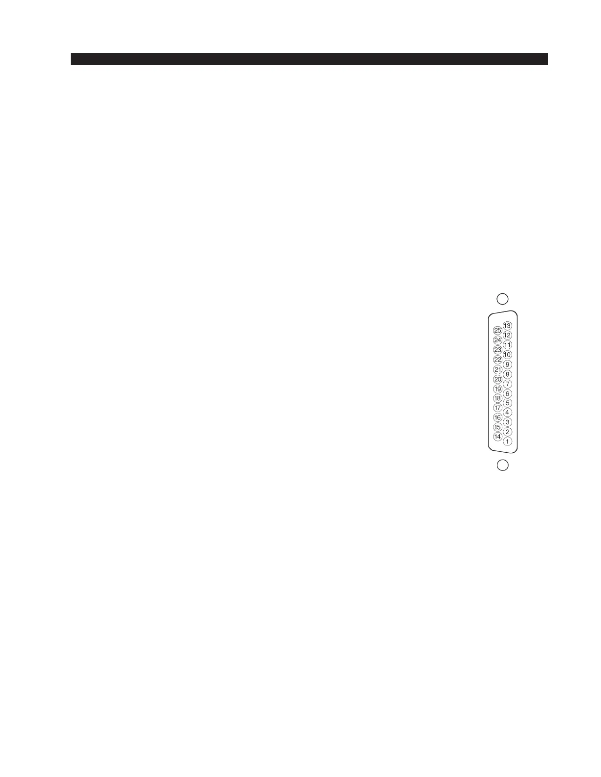
As stated before, all user wiring to and from SL-55e modules takes place
at the DB-25 multi-pin connector mounted on the top of each module. There
is one connector per module. Pinout drawings on page 3-7 show all wiring
connections at a glance.
Audio Connections
These include A and B source inputs; level is +4dBu balanced.
Pin 25 – Line A Lt In SH
Pin 24 – Line A Lt In HI
Pin 12 – Line A Lt In LO
Pin 11 – Line A Rt In SH
Pin 10 – Line A Rt In HI
Pin 23 – Line A Rt In LO
Pin 22 – Line B Lt In SH
Pin 21 – Line B Lt In HI
Pin 9 – Line B Lt In LO
Pin 8 – Line B Rt In SH
Pin 7 – Line B Rt In HI
Pin 20 – Line B Rt In LO
Control Connections
Functions include remote on and off, tally, ready, and start/stop for
remote source machines.
Pin 1 – Cough
Pin 2 – Ready
Pin 3 – Start
Pin 4 – Stop
Pin 5 – Start/Stop Com
Pin 6 – B Tally
Pin 14 – Remote On
Pin 15 – On Tally
Pin 16 – Remote Off
Pin 17 – TB to CR
Pin 18 – +5V Digital
Pin 19 – Digital Ground
Typical DB-25
connector
R-55e / Feb 2009