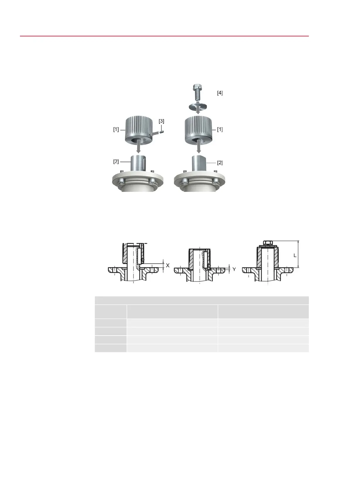
4. Place coupling [1] onto valve shaft [2] and secure against axial slipping by using
a grub screw [3] or a clamping washer and a screw with curved spring lock
washer [4].Thereby, ensure that dimensions X, Y or L are observed (refer to
figure and table <Mounting positions for coupling>).
Figure 6: Examples: Fit coupling
[1] Coupling
[2] Valve shaft
[3] Grub screw
[4] Clamping washer and screw with curved spring lock washer
Figure 7: Mounting positions for coupling
Table 3:
Mounting position of the coupling within fitting dimensions according to AUMA definition
EQ 300 – EQ 600EQ 40 – EQ 150Dimensions
[mm]
F07, F10, F12F04, F05, F07, F10EN ISO 5211
0.50.5X max
33Y max
5041L max
5. Apply non-acidic grease at splines of coupling (e.g. Gleitmo by Fuchs).
10
EQ 40 – EQ 150
Assembly EQ 300 – EQ 600