10. Setting the limit switching
.
Take off cover at switch compartment.
.
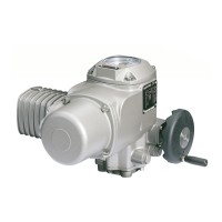
Pull off indicator disc (figure D). Open end spanner (approx. 14 mm) may
be used as lever.
These operation instructions are only valid for “clockwise closing”, i.e. driven
shaft turns clockwise to close the valve.
10.1 Setting for end position CLOSED (black section)
.
Turn handwheel clockwise until valve is closed.
.
Turn handwheel approx. 1 turn in direction OPEN and then half a turn in
direction CLOSED.
.
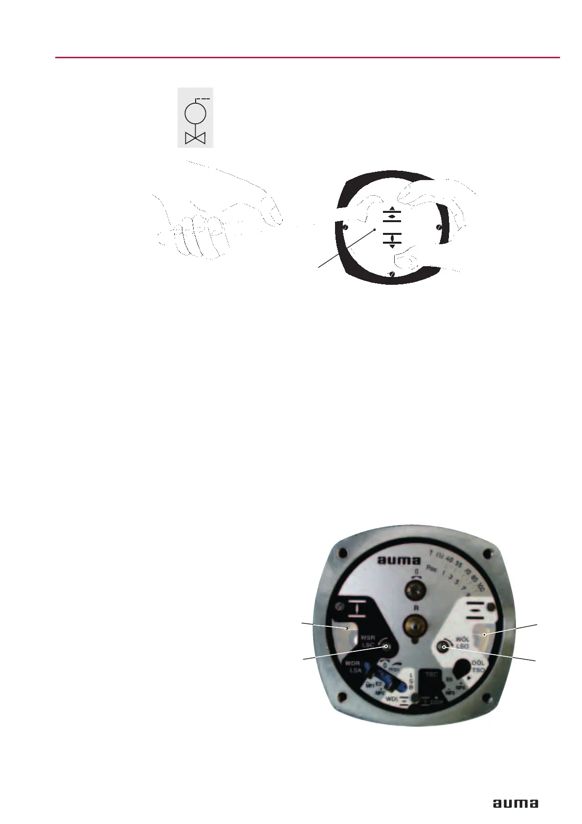
Press down and turn setting spindle A (figure E) with screw driver (5 mm)
in direction of arrow, thereby observe switch cam B. While a ratchet is felt
and heard, the switch cam B moves 90° every time. When switch cam B is
90° from the switch, continue turning slowly.
When the switch cam B snaps and trips the switch, stop turning and
release setting spindle.
If you override the tripping point inadvertedly (ratchet is heard after the
switch cam has snapped), continue turning the setting spindle in the same
direction and repeat the setting process.
11
Part-turn actuators SG 03.3 – SG 04.3
Operation instructions AUMA NORM
MOV
M
Figure D
Indicator disc
Figure E
A
A
B
B
 Loading...


